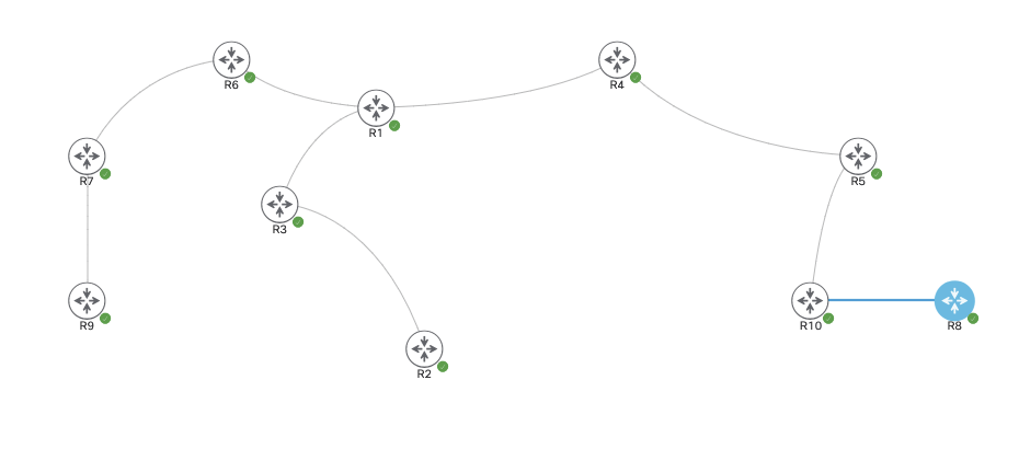
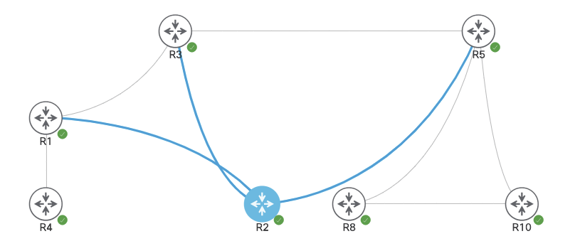
The image above shows 10 routers all running in OSPF area 0. They are each advertising their own loopback interface into the OSPF domain – ie. R<#> = #.#.#.#/24. They will each get Multicast and PIM Sparse mode enabled on their transit interfaces.
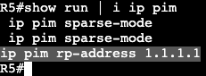
In addition, each router will point to R1 as it’s Rendezvous Point at 1.1.1.1.
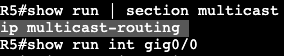
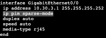
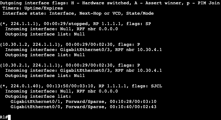
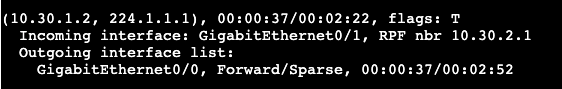
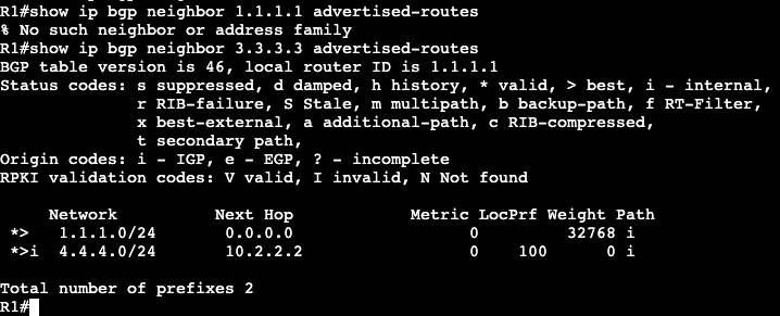
On R10 when trying to ping the multicast group 224.1.1.1, I will not get a response, but now on R1 there should be some information gathered.
‘show ip mroute’ on R1 will display a few things.
(10.30.1.2, 224.1.1.1) – Shows the sender (R10) and the group the sender was trying to reach (224.1.1.1). – Shows incoming interface on Gig0/3, RPF neighbor 10.30.4.1 (neighboring router interface). – Outgoing interface in regular Unicast table is Incoming interface in Multicast table.
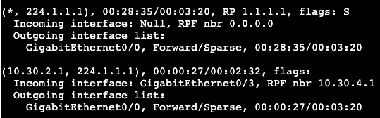
(*, 224.1.1.1) – Going to be used by the receivers. Right now it shows outgoing interface as NULL because there are no receivers.
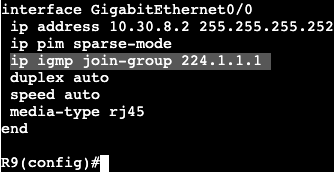
On the reverse side, lets now have a receiver ‘join’ the multicast group of 224.1.1.1. This will be completed in R9, where an IGMP join will be setup.
On R9 there’s only one link towards the RP, which is gig 0/0.
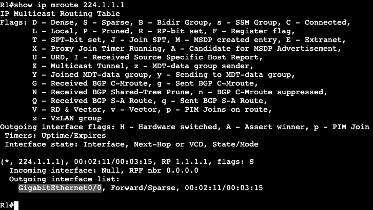
Now on the RP when looking at the group 224.1.1.1, there is an interface in the outgoing interface list. Gig0/0 is the interface pointing to R6, which is the closest to the new IGMP group member.
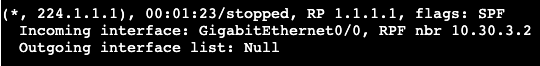
Now if we move up to R5 and take a look at the mroute table, we’ll see the following:
Shared tree that is pointed towards the Rendezvous Point (RP).
(S, G) – (Source, Group) – (*, 224.1.1.1)
And the source tree (Shortest path tree) which is rooted at the group sender.
(S, G) – (Source, Group) – (10.30.2.1, 224.1.1.1)
Notice the incoming interface is traffic coming from the source, and outgoing interface is where traffic goes to reach the RP.
The same can be seen on R4, which is another hop up the chain closer to the Rendezvous Point.
Mroute on R1 is going to show the shared tree and the (S,G).
SPT SWITCHOVER:
The RP is ultimately about creating the control plane for traffic from sender to receiver(s). If the RP is not actually in the data path between (S, G), then there’s no point in sending traffic to RP just to have it redirect to somewhere else. To accomplish taking the RP out of the next hop, SPT Switchover is completed.
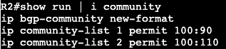
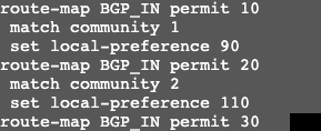
Using route maps avoids order of operations issues.
Regular Expressions
Used for the following:
Show command outputs
TCL/EEM scripting
BGP AS-Path access-lists
BGP Expanded Community lists
Info can be found in
IOS Terminal Services Configuration Guide
Appendixes
Regular expressions
Regex AS-Path access-list example
In the image below R1 and R4 are in ASN 200, R3 and R2 in ASN 100.
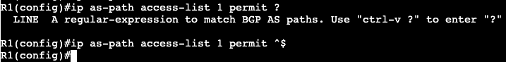
R4 and R1 have two originating routes being advertised into BGP, 4.4.4.0/24 and 1.1.1.0/24. The regular expression ‘^$’ can be used with BGP to show only routes that are originating from the local ASN. This can be used with an access-list/filter list with BGP to only advertise into BGP the locally originated, instead of passing on routes from external ASNs onto additional ASNs.
In IOS the command ‘show ip bgp regex ^$’ can be used to show only the locally originated routes being advertised.
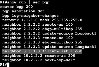
To create an ACL to filter down in BGP, the following can be completed.
The use of ‘filter-list’ on the neighbor statement then will only advertise out locally originated prefixes through the Regex ‘^$’.
BGP Max Prefix
BGP defaults to full view from all peers
Generally all prefixes should not get pushed upstream.
Can filter on number of prefixes
‘neighbor maximum-prefix’
Result can be log or shutdown peer.
BGP Outbound Route Filtering
Traditionally what providers will advertise out.
Full Table
Default Only
Default plus local (partial)
Outbound Route Filtering
Customer signals upstream what type of routes they want.
Results in control in customers hands vs. providers.
The ORF process can be configured with a prefix-list and then adding capability and prefix-list to a BGP neighbor statement. On R8 below we’re receiving all BGP routes from ASN 200 and 100 from R5. If we wanted to filter down to receiving one subnet from R5, 1.1.1.0/24, we specify that in the prefix list.
Now on R8’s BGP table, the local ASN prefixes and 1.1.1.0/24 are the only subnets available.
Soft Reconfiguration Inbound:
Saves unfiltered BGP routes received from peer in Adj-RIBs-In.
Adj-RIBs-In–>Loc-RIB–>Adj-RIBs-Out
Allows router to run ‘show ip bgp neighbor <neighor> received-routes
Takes up more memory because it’s saving another copy of inbound routes.
‘neighbor <address> soft-reconfiguration inbound’
Makes troubleshooting easier.
Before:
Route Refresh Capability:
Negotiated capability with OPEN message
Can ask peer to send an update without having to hard clear session.
‘clear bgp ipv4 unicast <neighbor> soft in’
‘clear bgp ipv4 unicast <neighbor> in’
‘clear bgp ipv4 unicast * in’
Does not consume memory like Soft Reconfiguration Inbound
Summarization can occur anywhere, unlike OSPF and IS-IS (link state)
Config
Under router bgp ASN process,‘aggregate-address <network><mask>’
config arguments
summary-only
suppress more specific routes
suppress-map
suppress subset of more specific routes
as-set
list of AS numbers and communities associated with the aggregate; inherited from more specific routes.
advertise-map
attributes of prefixes matched with advertised map are inherited in aggregate address
Used in conjunction with as-set
Prevents a specific AS from being included in AS_SET of the new aggregate.
Circumvents loop prevention
attribute-map | route-map
Used to modify attributes with aggregate address.
Used with as-set
Can set or remote attributes
E.g. remove “no-export” community, add MED.
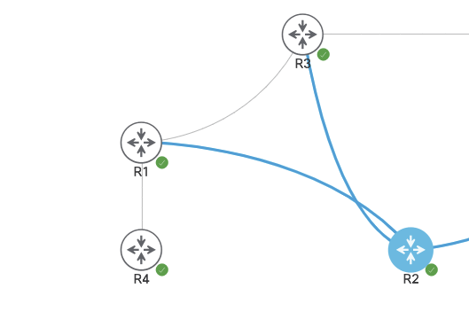
Topology:
R8, R10 = ASN 810.1 R5, R2 and R3 = ASN 100 R1 and R4 = ASN 200
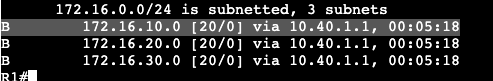
R10 is advertising subnets 172.16.10.0/24, 172.16.20.0/24, and 172.16.30.0/24 into BGP, which is seen in the route table of both ASN 200 routers.
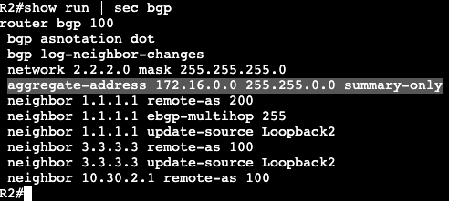
summary-onlyconfig: To summarize the subnets from R10 into ASN 200, we’ll have to add two commands to R2 and R3, which are the routers providing paths to ASN 200 for these IP ranges.
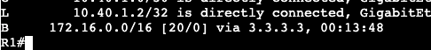
Now in the routing table on R1, we will only see the summary, and nothing else.
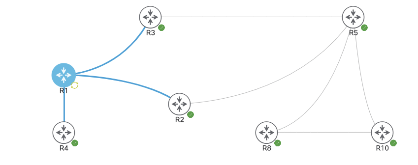
The next traffic engineering methods used will be MED and AS-Path. These are both methods to influence traffic coming inbound towards the Autonomous System. In the example below, R4 reaching R5 will have two paths via R2 and R3. The two paths can be seen to R5’s loopback with a ‘show ip bgp 5.5.5.5’. They’re both valid routes with equal attributes, but R2 is preferred probably because of a tie breaker that the neighbor has been there longest.
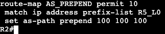
Currently both paths have the same AS length to reach R5, but to modify and prefer traffic to R5 through R3, we can set AS Prepend on R2.
Configuration:
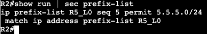
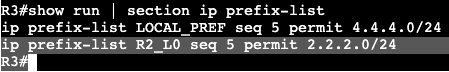
On R2 a prefix list, route-map and set to out will need to be applied. The prefix-list will match the loopback subnet of 5.5.5.0/24
The Route-map will match ip address to this prefix list.
And the route-map will then be applied outbound towards the neighbor we want to have a longer AS Path, router R1.
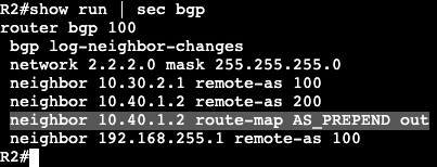
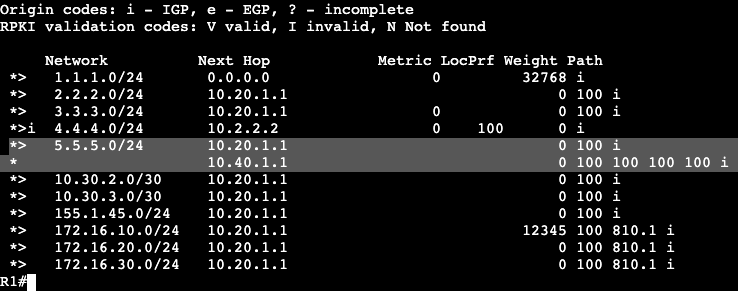
So again, R1 has two paths to subnet 5.5.5.0/24, one through R2 and one through R3. Adding AS-Prepend to the neighbor statement, we’re essentially saying the AS Path is now 4 Autonomous systems away instead of 1. This can be seen within a ‘show ip bgp’.
If we remove the AS-Prepend route-map we’ll see things go back to normal. The BGP table for R1 will have two even attributable routes to 2.2.2.2, but will only prefer one.
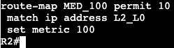
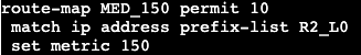
To modify inbound traffic with MED, we’ll need to go through a similar process. We’ll create a prefix list, route-map and assign to neighbor statements on both R2 and R3 toward R1. On R2 we’ll set the MED (metric) to 100, and R3 will be set to 150. Configs below, R2:
Config below, on R3:
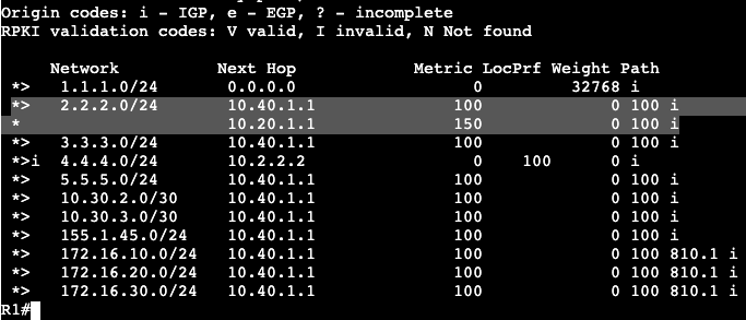
After this config is applied and the BGP clear ‘out’ has occurred, the route metrics will show differently in R1.
The route going through the next hop 10.40.1.1 is now the most preferred because Metric now shows 100, while 10.20.1.1 shows Metric of 150.
Note:
Both sides advertising a MED value should have something set. By default BGP without any value will be best.
bgp bestpath med missing-as-worst can override the default behavior.
In the image below there are 7 routers all running BGP.
The routers are running the following ASNs:
R1 and R4 – ASN 200
R2, R3, R5 – ASN 100
R8 and R10 – ASN 810.1.
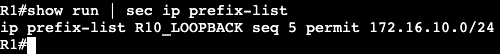
R10 is advertising three Loopback networks into BGP and we’re seeing how BGP will by default choose R1’s path to R10. On R1 there are two different paths to R10s loopback IP 172.16.10.0/24.
In the bottom right the router shows the path through R2 (2.2.2.2) is the ‘best’ – ie. best path. This can be seen in the routing table:
Going down the list for path selection, the weight is set to 0 on both and the local preference are both default 100.
AS Path length and origin can be seen in the image above as well – 100, 810.1, both the same.
The routes are so evenly matched that BGP will go down to the tie breakers, ie.
EBGP over iBGP
IGP Metric to Next Hop
Oldest
Lowest RID
Shortest cluster list
Lowest Neighbor address
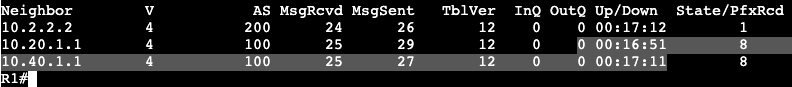
In this case BGP is selecting the neighbor going through R2 because it’s been exchanging routes for longer than R3.
To influence traffic outbound in BGP, we’ll need to send an advertisement inbound to R1. This will be accomplished typically with weight or local pref.
Configuration:
To modify by weight (Cisco proprietary) the first part of configuration will be a prefix-list and route map that can be applied inbound.
Next, the route-map needs to get applied inbound associated with the neighbor we want as more preferred – ie. R3 at 10.20.1.1.
The ‘clear ip bgp *’ refreshes inbound advertisements to the router. After the refresh, now we can see the route preference has changed to R3.
Weight can be seen as 12345.
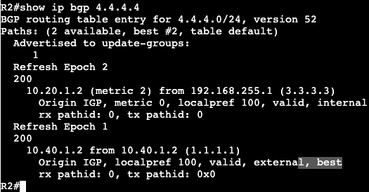
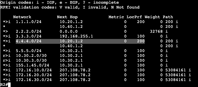
Next is a Local Preference example. In the image below we have the same ASN list, but now we’re looking at R4 and R2. R4 is advertising it’s loopback subnet 4.4.4.0/24 over into ASN 100, and we want to change how traffic from R2 chooses it’s path to R4.
R2 currently has two routes to reach 4.4.4.4/24, one through it’s iBGP neighbor at R3, and one through R1 via EBGP.
R2 will install this route into it’s routing table via its eBGP neighbor because the administrative distance is shorter and EBGP will be preferred over iBGP. To modify the local preference inbound to prefer R3, we’ll need to create a prefix list, then route-map, saying change the local preference via R3. Local preference is AS specific/spread, not just locally significant.
Prefix-List:
Route-Map:
R3 is receiving this route from R1, so the route-map needs to be applied under that neighbor inbound via router bgp <asn>. R3 and R1 are connected over the transit 10.20.1.0/30.
Now in R2 we can see that the best path is through R3 because the local pref is higher. This same local pref can be seen within the Autonomous System.
Once the advertisement leaves the local AS, Local pref is set back to the default 100.