Debugging logs all 0-7. Monitor will log to screen when remoting into device. Console logs to console when physically plugged into device.
Logs 0-7 to the local buffer.
Includes ms in the logs. Service timestamps allows changes in how logs appear in terms of time.
Conditional Debugging:
Allows logs to be generated for only specific things. Can be tied to access list.
The access-list was created permitting 10.10.10.10, then a route was created for that IP. In the logs we can see that there was a log generated for the additional static route.
Sending logs to host:
Sending to Syslog server 10.10.10.10; Only logging to level 4, warning.
‘show logging’ will display where we’re sending logs to, and what levels we’re logging at for monitor, console and buffer.
Allows tracking of IP service levels by using active traffic monitoring
Router generates packets to check service levels.
Used to measure and verify service levels.
QoS as example.
Uses different types of probes depending on app being monitored.
ICMP
TCP
UDP
Can be tied with object tracking to take actions.
Reliable static routes.
We’re running IP SLA examples between R5 and R4. R5 has a loopback with IP address 5.5.5.5 and R4 has loopback 4.4.4.4. The transit subnet is 10.30.1.0/24. R4 with .4 and R5 with .5. A backup path from R5 to R4 is through R3.
First config will just be ICMP from R5 to R4.
The only non-default configuration was changing the Threshold to a ping every 5 seconds. Next we need to schedule the ping for now and let it run forever. Then assign the SLA to a process for tracking.
The current reachability between the devices is completed with OSPF. What we can do though is add a static route that will take precedence over the OSPF AD of 110 and make the static depend on the IP SLA.
Once that is completed, the static route will be added or removed from the route table depending on the track succeeding.
After this we can add a floating static to R5 as well that has a higher administrative distance than our static with the track statement.
After shutting down the interface connecting R4 to R5, we see that the main static leaves the routing table and we have our alternate path with an AD of 15.
Next example is going to use TCP probes instead of just ping.
R5
R4
On R5 we created a tcp connect IP SLA and enabled forever. On R4 we had to create an IP SLA tcp responder for the IP and port we’re trying to hit. Now on R5 we can see the tcp connect is successful.
Same exact logic as the ping. We can change the tracking statement from IP SLA 1 to IP SLA 2, and now the tracking with the static route is taken care of.
Used to leak traffic from VRF table to global table.
Requires static routing with next hop and global keyword
‘ip route VRF1 0.0.0.0 0.0.0.0 gig0/1 1.2.3.4 global
NAT statement is VRF aware.
ip nat inside source list 1 interface gig0/1 vrf VRF1 overload
The topology above shows a host on the internal RFC 1918 network 192.168.10.0/24. R6 will be doing some NAT functions to the ‘Internet’. R6 has private IP on the link to host, and public on the link to R4.
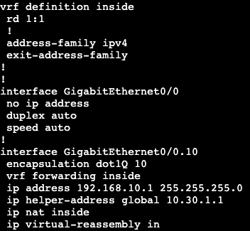
First configuration will be creating a new VRF and adding interface gig0/0.10 into it, which is the interface connecting to ‘Host’.
After adding the interface into the VRF we need to re-add the IP information like always.
This will cut off connectivity to the rest of the network because all of the routing is in R6’s global routing table, not the routing table associated with VRF ‘inside’.
To fix this we need to create a default route in the VRF to our next hop upstream, but specify the next hop is the global routing table. In addition, we’ll need to NAT traffic from the VRF to the outside interface. We’re going to do this with via an overload NAT/PAT.
Access-List permitting all
The default route here has a next hop of R4 and we’re pointing from the VRF to the global routing table.
And then we’re creating an overload NAT statement that references our VRF ‘inside’.
Now from our host we can reach past just our gateway/VRF on R6.
Destination IP rewrite may be used for redirection.
Normally configured as static mapping.
Port Address Translation
Many to one translation based on TCP/UDP ports.
Common overload.
Inside zone – networks translator wants to hide.
Inside local – Inside IPs before translation.
Inside global – Inside IPs after translation.
Outside zone – networks that are external to translator.
Outside Global – Original outside IP.
Outside Local – Outside IP after translation as its seen inside.
On the inside
Packets are first routed and then have sources translated.
Destination addresses are global so this is ok.
On the outside
Packets have destinations untranslated first.
Routing occurs after translation
Allows proper routing for returning packets with translated sources.
The topology above shows a host on the internal RFC 1918 network 192.168.10.0/24. R6 will be doing some NAT functions to the ‘Internet’. R6 has private IP on the link to host, and public on the link to R4.
Static 1:1
On R6 we need to first enter which interface is outside and which inside.
And the static 1:1 command:
Now if we telnet from ‘Host’ to ‘Internet’ at 8.8.8.8 and then look at the users on the box, we’ll see that the source IP address for the telnet session is the public NAT IP 96.76.43.140.
Can be seen on R6 that’s doing the NAT as well.
PAT/Overload:
1:1 has been erased off R6 and now we’re doing one to many PAT.
Access-list referencing the subnets that will use the PAT.
And the NAT statement that references the access list then specifies which interface we’re doing the port address translation on. ‘Overload’ at the end is needed as well.
Now when we run our telnet again to 8.8.8.8, we’ll see where we’re coming from.
We now get translated to R6’s ‘outside’ interface.
Policy NAT:
First we’re going to do a port forward from the ‘Internet’ router directly to the host. We’re going to pull an IP out of the IP block from the outside interface of R6. 96.76.43.141.
We are mapping the port 6500 and the IP of 96.76.43.141 to the inside port of 23 and the IP of 192.168.10.10. We can see this when looking at the nat translations from R6.
The topology above will have a DHCP server and relay setup. Host is going to be a DHCP client, R4 will be the DHCP server, and R6 will be our forwarder.
On R4 a DHCP pool has been configured for VLAN 10, the subnet in between R6 and eventually the host.
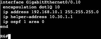
On the sub interface connecting to the host, we’ll need to add an IP helper statement towards the DHCP server, which allows DHCP requests to transit over L3 links.
The topology above has two gateways that will run GLBP, R6 and R4. The host is on the LAN side, 10.30.1.0/24, and the Internet has a loopback of 8.8.8.8.
The initial configuration only needs the one group command and VIP.
After this is on both LAN interfaces, the group is joined by the routers and we can see there are two forwarders, but only one active, R6.
To get the two routers both forwarding traffic, we need to run GLBP interface command for load-balancing.
Now when doing a traceroute from the host to 8.8.8.8, we see that the first attempt goes through 10.30.1.2 (R6), and a second attempt goes through 10.30.1.3 (R4). The round robin is every other and it goes by ARP request via client.
The above IP SLA and Tracking statement are still configured in R6 from the HSRP and VRRP configs. The tracking statement can get added to GLBP as well.
On R6 we’re going to decrement the default priority of 100 by 99 if the track fails, which is just pinging 8.8.8.8 on the ‘Internet’ router.
The topology above has two gateways that will run VRRP, R6 and R4. The host is on the LAN side, 10.30.1.0/24, and the Internet has a loopback of 8.8.8.8.
VRRP configuration is very straightforward and similar to HSRP. I entered the preempt command and it does not show up in a show run interface. That’s because it’s on by default.
Above shows the virtual MAC VRRP is using.
The authentication is the same as HSRP, but I created a new key chain for practice. This is the same for the tracking statement. If 8.8.8.8 on internet router goes down, the VRRP active member changes over.
Which shows on R4 when I shutdown the loopback interface.