What happens when someone types google.com into a web browser? Pt. 2

Continuation of Part 1 – https://mickx009.org/2020/03/22/what-happens-when-someone-types-google-com-into-a-web-browser-pt-1-dns-arp/

Per part 1, the computer in question now has received an answer to what public IP address Google.com maps to. With this information the computer can now begin a request to the server. The computer web browser will start by sending a request down from Layer 7 (application) to its layer 4 TCP stack requesting a socket stream with the destination port of TCP 443 (HTTPS). The TCP stack begins creating a segment with the destination port of HTTPS and source port from the OS random pool.

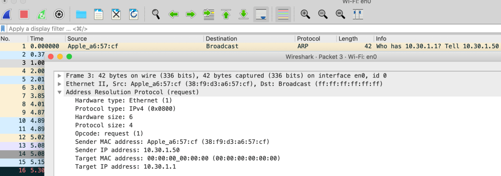
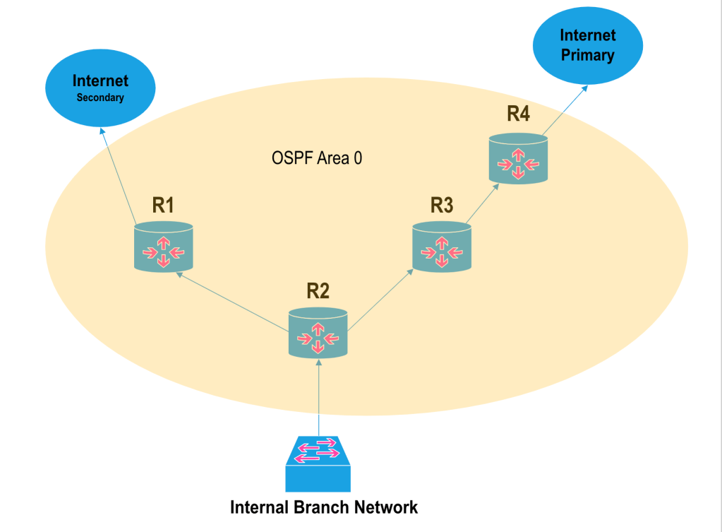
The TCP segment is then sent down to Network/Layer 3 where an additional IP header is added to the TCP segment. The IP header will contain both a source and destination IP address. The destination IP is the public IP the DNS query received mapping to Google.com. The source IP will in theory be the IP address assigned to the computer trying to reach Google.com. After the IP header is added to the segment, the networking stack then sends the now IP packet down to Layer 2 where a Frame header is added on. The Frame header includes the source MAC address, which is the hardware address associated with the computer NIC, and the destination MAC address that is assigned to the default gateway. Part 1 showed that the computer now knows the MAC address of the default gateway due to the ARP broadcast process. If the local computer for some reason does not know the MAC address of the router/gateway, then the ARP process would need to be run again. From here the now Frame is sent to the local router/gateway where the Frame header is taken off the IP Packet. The router then processes how to reach the destination IP of the packet via the device’s routing table. Most likely a Default Route entry is found in the routing table which tells the router where to send the incoming traffic. Before the computer Packet is sent off, the router first will add another Frame on top of the Packet. The Frame will once again have a source and destination MAC address. The source being the WAN side of the router MAC address, and the destination being the MAC address of the next hop router interface. The hopping between Layer 3 and Layer 2 will continue until the destination is reached. And ultimately continue in both directions until the computer sends and receives all necessary payload.

It’s worth mentioning that in a typical Enterprise/Residential network, internally the hosts are using IPv4 RFC 1918 address space. This address space is not usable on the public internet, so most internet users require their router to perform NAT to reach the IPv4 internet. At the edge of the network before reaching the internet, a router will typically perform a 1 to many Network Address Translation. This means all internal RFC 1918 hosts will get translated to one public IP address assigned to the WAN/public side of the router. All traffic internet bound will appear to be coming from that one public IP. Sessions are managed via internal and external source/destination layer 4 ports.

When the computer in question reaches the server hosting Google.com, the server receives the Frame, removes layer 2 and layer 3 headers, then processes the segment on the server’s listening TCP port, in this case 443. The received segment has the SYN flag set which starts the beginning of a TCP connection. The server responds back to the computer with the SYN ACK flags set, then receives a response back from the computer with a final ACK. The final ACK is the end of the initial three way handshake and data can start getting transmitted between the server and computer.

What happens when someone types google.com into a web browser? Pt 1. DNS & ARP

I realized that I’ve been asked the question What happens when you type <insert website> into a browser? in a lot of interviews, and I’m not sure I’ve ever answered well. I always fumble my way through it and realize I’m thoroughly missing steps. I’m going to try and answer this from the perspective of interviewing for a Network Engineer/Admin position, so more networking focused than anything else. I’m also going to operate under the assumption this is IPv4 and there are no local caches, MAC table entries, etc. Surely I’ll miss some steps, these can probably be some ongoing write ups that get updated over time.

When someone enters google.com into a web browser the first thing from a networking perspective (besides OSI Layer 1) that needs to happen is IP address resolution. The computer needs to know what IP address the website has and this is found through a DNS query. The computer’s network stack will have a DNS client configuration that points to a known DNS server. Lets say for this example the computer has the server 8.8.8.8 configured for DNS. In this case, the computer will attempt to send a DNS query to the DNS server at IP address 8.8.8.8 over UDP port 53. The layer 4 protocol and port number are not a guarantee but currently more often than not UDP 53 is what will be used.

On both residential and enterprise networks we typically see RFC 1918 address space – ie. internal, non public space. In this example lets assume the PC has the internal IP address of 10.30.1.50/24. When the computer needs to reach an IP address that is not on its local subnet (10.30.1.0/24), it will send its traffic to whatever IP is assigned to its NIC’s Default Gateway (10.30.1.1). Because the IP address 8.8.8.8 does not fall into the IP range of the local subnet, the computer will try and send its DNS query to its default gateway at 10.30.1.1.

Moving from IP (layer 3) to Ethernet (layer 2), for a computer to forward datagrams and frames over an ethernet network it needs to know destination MAC addresses. In this scenario the PC needs to forward its DNS query to the router/layer 3 device that has the assigned IP 10.30.1.1. To find this MAC address the computer will send out what’s called an Address Resolution Protocol (ARP) request. The ARP request is a layer 2 broadcast that gets forwarded to every device in the layer 2 broadcast domain, such as a VLAN. The layer 2 ARP broadcast (ff:ff:ff:ff:ff:ff) is essentially asking every device ‘who has the IP address 10.30.1.1?’, and the only device that responds to the request is our router that allows access out to the public internet.

Once the router/default gateway responds to the ARP request the computer is then able to send out a DNS query to the public internet which routes the query to the nearest point of presence for 8.8.8.8. Public DNS servers like 8.8.8.8 or ISP provided DNS servers are typically called Recursive DNS Servers. If the Recursive DNS server knows what the public IP address is for ‘Google.com’ then it immediately responds back to the computer with the answer. If the recursive DNS server does not know then it will send a request to one of the Internet’s 13 Root Nameservers. The root nameserver will respond to the request with one of the Top Level Domain (TLD) Nameservers, depending on the end of the domain name – ie. .com, .net, etc. The TLD nameservers will then respond to the recursive server with the final Authoritative Nameserver that knows what IP address maps to the domain Google.com. The Authoritative Nameservers are DNS hosting providers such as GoDaddy. Once the recursive DNS server receives the IP address it then caches the information so that the DNS query process from the client is answered right away the next time.

Now that the computer has successfully received an answer for the DNS query, it now can start the process of requesting data from the server hosting Google.com.

Floating Static Route – Backup Default

The floating static route is a quick tool for directing traffic to destinations a different way through the network when default metrics work against us or there is a link failure.  In conjunction with dynamic routing protocols, a network operator can use the floating static route and route table Administrative Distance to manipulate traffic flows.  

Branch Office

In the diagram above you’ll see a small OSPF area with two exit points to the internet.  The business has asked you as the network operator to have the primary route to the internet for the branch via R2 –> R3 –> R4.  The secondary or backup internet connection is accessed via R2 –> R1.  Lets say all links are equal speed/cost in terms of OSPF metrics and both internet gateways are advertising their respective default quad 0 (0.0.0.0/0) route into the OSPF area.  If that’s the case then due to OSPF cost value R2 will install the secondary default route into its forwarding table instead of the primary.  An option to direct internet bound traffic to R3/R4 would be to have R1 stop advertising its quad 0 into the OSPF domain, but then R2 doesn’t know about the secondary connection when the link between R2 and R3 fails.  A quick way of getting around this issue is by utilizing a floating static route on R2.

By default a router uses Administrative Distance (AD) to choose best path through a network when there are two routes to the same destination. The AD value of a route is typically dependent on how the routing device received the route entry, and the lower the value the more preferred the route. The typical default routing protocol AD values are below, although this is not exactly the same for all vendors.

Administrative Distance Values:

  • Static – 1
  • EBGP – 20
  • EIGRP – 90
  • OSPF – 110
  • iBGP – 200

Going back to the diagram above, if we need R2 to have a backup quad 0 route to R1, we can add a static route pointing to the next hop assigned to R1. But per the AD values list, a static route entry has a value of 1, which is preferred over the dynamic protocols. To get the static route to function as a less preferred option the route entry needs to be added into the route table with an AD value higher than the quad 0 routing table entry advertised by R3 through OSPF. OSPF has an AD value of 110 by default, so modifying the static route to the secondary internet connection with the value of 111 will successfully make the OSPF route more preferred.

Cisco – R2(config)#ip route 0.0.0.0 0.0.0.0 <R1 Next Hop> 111

As a result the R2 routing table will have a quad 0 default route with a next hop of R3. If the link between R2 and R3 ever goes down the default route pointing to R3 will dynamically be taken out of R2’s routing table and the backup ‘Floating’ static route will emerge. Once connectivity and OSPF adjacency come back the OSPF default route will once again take priority.

There are other ways to solve the problem but the floating static route is quick and overall straightforward. Someone asked me what this was once and I didn’t know what they were talking about. For some reason I’d never called this function a ‘Floating Static Route’ even though I’d used and seen it multiple times before. It’s a fitting name.

Security Associations – IPSEC Tunnels (IKEv1)

IP Security (IPSEC) was created by the IETF to provide a collection of protocols that allow for safe and secure transmission of data over the public internet. IPSEC is basically a grouping of authentication and encryption algorithms. The IPSEC concept for instance was not created with a specific encryption algorithm to be used, instead the decision of how security measures should be used is up to the network operator(s). When setting up an IPSEC site to site tunnel, the term Security Association (SA) is very important. The SA is the security scheme or collection of security mechanisms each peer has agreed upon and will use when transmitting data over the tunnel.

There are two types of SAs when building an IPSEC tunnel, the IKE SA and the IPSEC SA. As most operators know there are two phases that need to be completed before an IPSEC tunnel is fully operational, and the IKE SA is phase 1, IPSEC SA is phase 2.

In IPSEC phase 1 the items typically configured are authentication, encryption, Diffie Hellman group number, SA lifetime, and pre-shared key. Both IKE peers with IKEv1 need to have identical configurations for phase 1 to complete. Once phase 1 has completed the IKE SA has been established between the two peers. This SA allows for a secure communication between the two endpoints, allowing them to establish the needed phase 2 IPSEC SAs. The IKE SA in my point of view is almost like a management SA – a secure channel for the peers to negotiate the actual tunnel (phase 2). This SA is bidirectional, allowing communication back and forth.

As stated above, in phase 2 of building an IPSEC tunnel we run into IPSEC SAs. Some IPSEC SA configuration examples below:

  • Destination Address – IPv4 typically internal RFC 1918
  • IPSEC Transforms – Encryption and Authentication
  • IPSEC SA Lifetime – Typically seconds
  • Replay Detection – Replay Attack Detection
  • Perfect Forward Secrecy – DF Group – Optional

A large difference between the IKE SA and the IPSEC SA is that the IKE SA is a single SA for bidirectional communication between the two peers. IPSEC SA consists of two separate SAs which are each unidirectional. Each IPSEC SA consists of a group of security policies to be agreed upon and used, but there’s one SA for inbound traffic and one SA for outbound traffic. Another way of looking at it is there’s one SA for decrypt (inbound) and one SA for encrypt (outbound). The phase 2 portion of an IPSEC tunnel/SA is what’s actually moving and securing user datagrams.

A portion of the IPSEC SA is the Security Parameter Index (SPI). The SPI is actually a unique key value created by an IPSEC peer that is applied to each SA. When a datagram is transferred over an IPSEC tunnel, the SPI value is passed along in the IPSEC header. Once the datagram is received the peer looks up the SPI value and destination address. With these two pieces of information the receiver knows how to process the packet along.

Although not always needed, its very helpful to have an understanding of what a Security Association is when troubleshooting problems that have to do with IPSEC tunnels.