FortiClient SSL VPN – DHCP

Someone reached out recently and told me that a Fortinet Fortigate SSL VPN was acting up and DHCP was not working correctly. This person was receiving the Windows error message on their PC while working remote that there was a duplicate address problem.

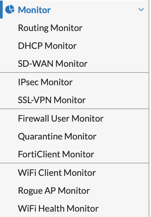
The problem I believe wound up being something on that person’s home internal network, but I did attempt to look into the issue right away and could not find a lot of information on DHCP leases for the Fortigate SSL VPN IP range. As any Fortigate admin knows, one can log into the GUI and go to Monitor–>DHCP Monitor, or Monitor–>SSL-VPN Monitor. From there you can view all DHCP leases (if you’re using the firewall as a DHCP server) or view all active SSL VPN connections.

GUI SSL-VPN Monitor can be viewed in CLI via below:
#get vpn ssl monitor

I never thought about it before but I assumed I could see DHCP leases for the SSL VPN IP range in the DHCP monitor window, but there was nothing when I tried. Under the SSL VPN monitor however I could see numerous connections with valid IPs for the VPN range.

I looked into this a bit to find DHCP lease information for the VPN and apparently the DHCP daemon does not actually hand out IPs to VPN clients. The VPN clients get IP address information from the sslvpn daemon itself. DHCP options such as lease time do not exist because of this. The SSL VPN DHCP lease time is essentially the time of the VPN connection. Once the VPN connection is removed, that IP goes straight back into the IP pool for the next incoming SSL connection.

Seems somewhat obvious after typing this out, but still glad I did.

FortiClient SSL VPN Timeout

Due to the global COVID-19 pandemic there have been many people switching from working in the office to telecommuting at home. This has required many individuals who are not typically used to working remote get used to operating a VPN client.

An issue we kept running into was a report that every day at a specific time the FortiClient VPN connection would drop. The odd thing was that this specific time of dropping was the same time for the same person, but not the same time across all users having the issue. Eventually we traced the issue back to someone who started work everyday at about 5:45 AM and everyday the connection would drop at 1:45 PM. This lead us to find out what the default SSL VPN timeout setting was for Fortigate SSL VPN access. Per below, the default timeout setting for an SSL VPN client was 28800 seconds – ie. 8 hours.

After some discussion we decided to increase the timeout value to 43200 – 12 hours.

Once the commands were entered on the Fortigate above these disconnect reports went silent.

Fortigate Link Monitor – (Cisco IP SLA Equivalent)

In an office or branch location that relies on internet access for productivity, it’s obviously typical to see a primary and secondary internet connection from two separate providers. In IPv4 world if you are not using your own IP space and BGP peering with the upstream providers, then automatic failover when the primary connection goes down becomes a concern. In a simple active/passive two ISP to one router (dual homed) setup, the router/firewall will have two static default routes for each provider. Each route will have a weight or metric determining which one is more preferred. Active/Active connections is an option, especially now with the rise of SD-WAN solutions, but often times a simple active/passive is what’s needed. In Fortinet world the metric for active/passive is Distance. The lower the Distance the more preferred the route.

In the image above the primary ISP route will be used due to the distance value of 1. But how does the firewall know when the Primary ISP is having issues and needs to stop sending internet bound traffic that way? With this configuration by itself, the only way the firewall will remove the default route to our primary ISP is if the interface on the device itself goes down. As most network operators know, it’s very common for a physical interface on a router/firewall to stay up, but the modem or somewhere upstream is actually not working. What we really need to do for this situation is setup what Fortinet calls a Link Monitor (previously called Dead Gateway Detection).

The function of the Link Monitor is to take an interface and continuously try and call out to an IP address up stream. ‘Call out’ to an IP address means ping, tcp/udp echo, or http query. But the general idea for this scenario is if the Fortigate can access something upstream then the internet connection must be alive and well. If after the specified link monitor failure attempts occurs, then the firewall will either shut down the Primary ISP interface or simply update the routing table. In the configuration example below the firewall is set to ping 8.8.8.8 out the Primary ISP interface.

SETTINGS OF IMPORTANCE:

set interval 2 = Time in seconds between sending link health check packets. Set to 2 seconds.

set failtime 5 = Number of times a health check can fail.

set recoverytime 10 = Number of times health check must succeed to verify connection is back up.

set update-static-route enable = Removes static route from routing table if link monitor fails.

In our dual homed example the Fortigate sends a ping to 8.8.8.8 out WAN1 connected to the Primary ISP every 2 seconds. If the ping fails to reach 8.8.8.8 five times in a row then the default static route is removed from the firewall routing table and the secondary default static route takes over. Once the ping succeeds over the Primary ISP interface 10 times, the default static route is added back.

The configuration above is what I’ve used in the past successfully which differs from the Fortinet Link Monitor defaults. With the default settings I’ve had issues with flapping between connections. Every situation is different but the configuration above for internet connections is what I’ve had the best luck with. The Link Monitor feature is what Cisco world calls an IP SLA.

Fortigate SSL VPN – Redistribution into OSPF

I recently had to setup remote access SSL VPN for a customer on a Fortinet firewall. The network runs OSPF internally and the customer asked we integrate the SSL VPN into their IGP. It’s a simple OSPF implementation that utilizes a VPLS leased line from their provider as a primary route to their COLO and a secondary IPSEC tunnel if the leased VPLS circuit goes down. OSPF handles the automatic failover.

First we went through the steps of configuring the SSL VPN, new IP range, user groups, LDAP settings, public DNS records, etc. After confirming we could successfully connect to the firewall remotely, we had to then setup the firewall to advertise into OSPF the new remote access IP range. Once the new prefix was added to the advertised networks list I began checking the routing table of other OSPF router participants. After all the neighbor adjacency was already in place, but low and behold the new IP range failed to show in the neighboring route tables. After doing a bit of research I discovered that the Fortinet firewall will only advertise the SSL VPN prefix through static route redistribution. The firewall operator must setup the appliance with a blackhole static route to the prefix, and then configure the firewall to redistribute static routes into OSPF.

The main problem with the solution above is that you may not want to redistribute every static route on the appliance into the OSPF domain. The below redistribute button in the UI is an all or nothing option.

A method of filtering static route redistribution on the firewall (like many networking devices) is to use Route Maps. Route Maps are a great way to define routing policy and customize redistribution into varying routing protocols.

First step is to create the Blackhole static route that we will then advertise into our OSPF domain. In the UI go to Network–> Static Routes –> and enter the following (whatever the new remote access IP Range is):

Once the static route’s in place the next step is to create an IP Prefix list. Hop into the appliance CLI and use the below commands.

The first configured rule is to match the SSL VPN IP Range, and the second is to deny all other IP ranges. Once prefix list is done the next task is to create the Route Map with the prefix list reference per below.

The last steps to finish is enabling static route redistribution into OSPF and to apply our new Route Map to the redistribution. The below few commands will get the task completed.

Barring the new prefix is in the network statements of the Fortigate firewall, after all of this you should start seeing the new IP range advertised into the OSPF autonomous system. The above can be done as well with an IP Access List on the Fortigate Firewall, but I find the prefix match list an easier method.

Fortinet Source-IP – Interface

A co-worker of mine a bit ago setup a Radius server for all of our small branch offices. The idea was a central Radius server for internal wireless authentication at all branches, each with a smaller Fortigate firewall appliance. Each Fortinet appliance would act as the Radius client, initiating a connection to the central Radius server in a COLO.

Each site leveraged the public internet to create IPSEC tunnels back to a VPN concentrator in the COLO facility. There were no leased private lines, all internal connectivity to the rest of the corporate network was through dual site to site VPN tunnels.

After confirming the Radius server worked locally in the COLO, we took one of the branch firewalls and setup the Radius client. For a simple Radius client setup in a Fortinet appliance there’s not much to it. Add the IP of the Radius server (or IPs for primary and secondary servers) and then enter the Radius key for authentication. Once the Radius client configuration is entered, you then just need to make sure a policy is allowing the branch internal network to reach the Radius server on TCP and UDP ports 1812 and 1813. This is assuming the IPSEC tunnel and proper routing is available to reach the subnet the Radius server resides on.

We configured the client and tried testing the connectivity, but for some reason we found the Fortinet appliance (Radius client) could not connect to the Radius server on the proper ports. We could confirm from the internal side of the firewall, a PC for instance, could reach the Radius server properly, but just not the firewall. After running a packet capture on all interfaces with a host address of the Radius server IP, we discovered that the firewall was in fact attempting to reach the server, but only out its management interface, not the internal interface/subnet we wanted it to. After looking into the CLI we found an option within the Radius server configuration to specify a source IP address/interface.

Commands from Above
config user radius
edit <Radius Client Name>
show full

What we discovered was that in Forti-OS world when specifying a target on the appliance that is not part of a directly connected subnet, the operator often times needs to specify an interface to use for reaching the destination. This appears to be true for some other functions on Fortinet firewalls as well, such as LDAP. If an LDAP server is specified on the firewall but is not within a directly connected network, chances are the operator will need to specify what interface to use for reaching that LDAP server. In our example with the appliance reaching the Radius server, we needed to specify the IP address assigned to the internal interface that is associated with a subnet already capable of reaching the Radius server subnet. After entering the source-ip we immediately were able to connect the Radius client to the Radius server over our IPSEC tunnel.