Blog Feed

AWS Transit Gateway – Active/Passive IPSEC Tunnels

Like so many others, my organization over the last few years has been leveraging AWS cloud services for IT infrastructure.  It started out with one account, one VPC, one VPN tunnel (2 for redundancy) and a handful of EC2 instances.  Gradually over time this simple cloud presence has multiplied drastically.  There are now numerous EC2 instances, VPCs, VPN tunnels, regions in use, and AWS accounts.  I was not around to witness this AWS footprint grow; I inherited the network responsibilities after the fact. 

When arrived I investigated the on premises to AWS connectivity and discovered the web of data center to VPC VPN tunnel networking.  Setting up internal connectivity from an on prem router/firewall to a VPC is relatively straight forward.  In AWS you follow the steps here to setup a site to site IPSEC tunnel and then download a configuration ‘walk through’ to configure your physical device where you want connectivity.  Each VPN tunnel you configure on the AWS side results in two tunnels to your on prem gateway for redundancy.  In the end on the customer network side you get two VPN tunnels to every VPC needing internal network connectivity.  As one can imagine this doesn’t scale very well.  Even 15 AWS VPCs results in 30 VPN tunnels with 30 separate BGP peers or static routes depending on which option you go for in terms of routing.

I was able to simplify my org’s cloud networking by utilizing AWS’ Transit Gateway service.  A Transit Gateway (TGW) essentially moves your cloud networking architecture to a hub and spoke model.  Instead of setting up direct connections from your data center to each VPC separately, each VPC is connected to the TGW and the local router/firewall has an IPSEC VPN tunnel only connecting to the TGW as well.  The TGW allows for all internal connectivity between VPCs and on prem.  Per the example above, moving to a TGW hub and spoke you would go from 30 VPN tunnels to two.  The two VPN tunnels to the TGW are for redundancy and equal cost multi-path if you want to go the ECMP route.     

    Example Before:

    Example After:

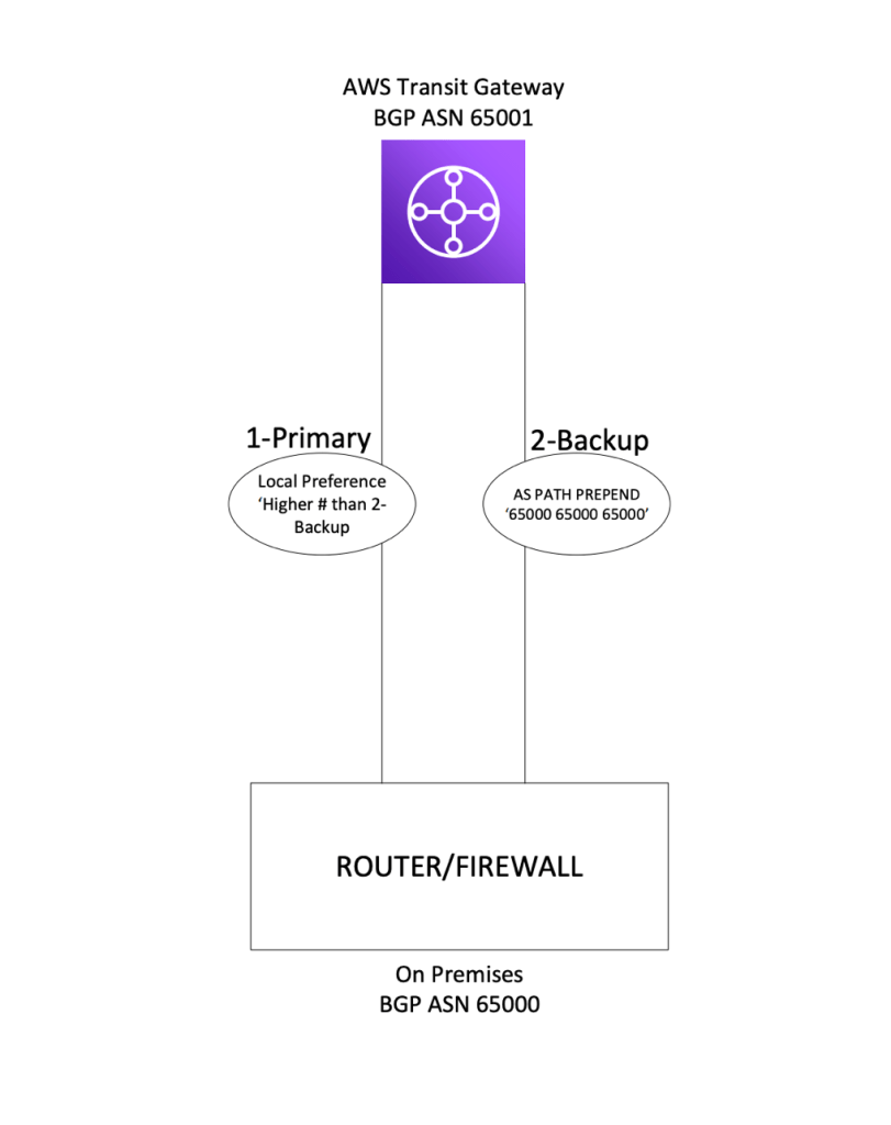
Per the AWS Transit Gateway documentation, the maximum bandwidth per VPN connection is 1.25 Gbps which exceeds the bandwidth of the internet connection the org is using to terminate the site to site tunnel.  This means ECMP is not needed and an active/passive tunnel approach is more suitable.  An issue I ran into while setting this up had to do with tunnel priority and BGP.  I discovered that when setting up a standard VPN tunnel direct to VPC, AWS will advertise routes to an on prem device over BGP with a MED value of 200 for one tunnel and 100 for the other.  This allows for a primary and secondary tunnel, avoiding asymmetric routing, etc.  However, when two tunnels are configured to a TGW AWS does not advertise routes to a customer on prem device with different MED values.  This obviously is an issue if you’re looking for an active/passive approach with zero ECMP.

After digging around AWS documentation and the internet I discovered that BGP peering to a TGW will in fact honor AS Path Prepend.  As a result I was able to use AS Path Prepend on the routes advertised over the secondary tunnel, and Local Preference on the routes advertised to our on prem device from AWS over the primary tunnel.

I believe these same BGP attributes can be used for AWS DirectConnect customers as well.

For some reason I struggle to find proper AWS documentation and setting this up took longer than it needed to.  I hope this will save someone some time if they run into this same situation.

Fortinet Source-IP – Interface

A co-worker of mine a bit ago setup a Radius server for all of our small branch offices. The idea was a central Radius server for internal wireless authentication at all branches, each with a smaller Fortigate firewall appliance. Each Fortinet appliance would act as the Radius client, initiating a connection to the central Radius server in a COLO.

Each site leveraged the public internet to create IPSEC tunnels back to a VPN concentrator in the COLO facility. There were no leased private lines, all internal connectivity to the rest of the corporate network was through dual site to site VPN tunnels.

After confirming the Radius server worked locally in the COLO, we took one of the branch firewalls and setup the Radius client. For a simple Radius client setup in a Fortinet appliance there’s not much to it. Add the IP of the Radius server (or IPs for primary and secondary servers) and then enter the Radius key for authentication. Once the Radius client configuration is entered, you then just need to make sure a policy is allowing the branch internal network to reach the Radius server on TCP and UDP ports 1812 and 1813. This is assuming the IPSEC tunnel and proper routing is available to reach the subnet the Radius server resides on.

We configured the client and tried testing the connectivity, but for some reason we found the Fortinet appliance (Radius client) could not connect to the Radius server on the proper ports. We could confirm from the internal side of the firewall, a PC for instance, could reach the Radius server properly, but just not the firewall. After running a packet capture on all interfaces with a host address of the Radius server IP, we discovered that the firewall was in fact attempting to reach the server, but only out its management interface, not the internal interface/subnet we wanted it to. After looking into the CLI we found an option within the Radius server configuration to specify a source IP address/interface.

Commands from Above
config user radius
edit <Radius Client Name>
show full

What we discovered was that in Forti-OS world when specifying a target on the appliance that is not part of a directly connected subnet, the operator often times needs to specify an interface to use for reaching the destination. This appears to be true for some other functions on Fortinet firewalls as well, such as LDAP. If an LDAP server is specified on the firewall but is not within a directly connected network, chances are the operator will need to specify what interface to use for reaching that LDAP server. In our example with the appliance reaching the Radius server, we needed to specify the IP address assigned to the internal interface that is associated with a subnet already capable of reaching the Radius server subnet. After entering the source-ip we immediately were able to connect the Radius client to the Radius server over our IPSEC tunnel.

Security Associations – IPSEC Tunnels (IKEv1)

IP Security (IPSEC) was created by the IETF to provide a collection of protocols that allow for safe and secure transmission of data over the public internet. IPSEC is basically a grouping of authentication and encryption algorithms. The IPSEC concept for instance was not created with a specific encryption algorithm to be used, instead the decision of how security measures should be used is up to the network operator(s). When setting up an IPSEC site to site tunnel, the term Security Association (SA) is very important. The SA is the security scheme or collection of security mechanisms each peer has agreed upon and will use when transmitting data over the tunnel.

There are two types of SAs when building an IPSEC tunnel, the IKE SA and the IPSEC SA. As most operators know there are two phases that need to be completed before an IPSEC tunnel is fully operational, and the IKE SA is phase 1, IPSEC SA is phase 2.

In IPSEC phase 1 the items typically configured are authentication, encryption, Diffie Hellman group number, SA lifetime, and pre-shared key. Both IKE peers with IKEv1 need to have identical configurations for phase 1 to complete. Once phase 1 has completed the IKE SA has been established between the two peers. This SA allows for a secure communication between the two endpoints, allowing them to establish the needed phase 2 IPSEC SAs. The IKE SA in my point of view is almost like a management SA – a secure channel for the peers to negotiate the actual tunnel (phase 2). This SA is bidirectional, allowing communication back and forth.

As stated above, in phase 2 of building an IPSEC tunnel we run into IPSEC SAs. Some IPSEC SA configuration examples below:

  • Destination Address – IPv4 typically internal RFC 1918
  • IPSEC Transforms – Encryption and Authentication
  • IPSEC SA Lifetime – Typically seconds
  • Replay Detection – Replay Attack Detection
  • Perfect Forward Secrecy – DF Group – Optional

A large difference between the IKE SA and the IPSEC SA is that the IKE SA is a single SA for bidirectional communication between the two peers. IPSEC SA consists of two separate SAs which are each unidirectional. Each IPSEC SA consists of a group of security policies to be agreed upon and used, but there’s one SA for inbound traffic and one SA for outbound traffic. Another way of looking at it is there’s one SA for decrypt (inbound) and one SA for encrypt (outbound). The phase 2 portion of an IPSEC tunnel/SA is what’s actually moving and securing user datagrams.

A portion of the IPSEC SA is the Security Parameter Index (SPI). The SPI is actually a unique key value created by an IPSEC peer that is applied to each SA. When a datagram is transferred over an IPSEC tunnel, the SPI value is passed along in the IPSEC header. Once the datagram is received the peer looks up the SPI value and destination address. With these two pieces of information the receiver knows how to process the packet along.

Although not always needed, its very helpful to have an understanding of what a Security Association is when troubleshooting problems that have to do with IPSEC tunnels.

TCP Congestion Avoidance – NOTES

TCP Congestion Avoidance works alongside Slow Start to make sure a TCP connection is not being overrun with too much data. After a connection is established the Slow Start mechanism begins and the sender window continues to increase exponentially. Each acknowledgement the sender receives warrants the sending window size to double.

  • SENDER –> 1 Segment
  • RECEIVER –> 1 ACK
  • SENDER –> 2 Segments
  • RECEIVER –> 2 ACKs
  • SENDER –> 4 Segments
  • RECEIVER –> 4 ACKs
  • SENDER –> 8 Segments
  • RECEIVER –> 8 ACKs

A value created when establishing a TCP connection is the Slow Start Threshold (ssthresh). The ssthresh is used by the sender to know whether the TCP connection is in the Slow Start phase or the Congestion Avoidance phase. If the ssthresh is greater than the Congestion Window (CWND) then the TCP connection is in the Slow Start phase. The Slow Start phase will continue exponential growth (double amount of segments per ACK) unless there is data loss on the connection. If the ssthresh is larger than the CWND, then the TCP connection is in the Congestion Avoidance phase. In the Congestion Avoidance phase the CWND is increased by 1 segment only if ALL segments in the window have been acknowledged by the receiver. The idea is to slow down the increasing rate of transmitting data to stabilize the link or utilize the proper amount of physical bandwidth available.

The sender would discover loss/congestion over the connection through either receiving 3 of the same ACKs or a retransmission timeout (no ACK received after timer). If a sender deems there is segment or data loss over a connection then CWND is decreased to 1 MSS and the slow start process begins again.

EXTRA NOTES-

  • There are different versions of TCP that are more beneficial for LFNs, Long Flat Networks.
  • ssthresh is calculated differently sometimes. Sometimes the value is set to infinite, meaning the CWND will grow infinitely until loss occurs.

TCP Slow Start – NOTES

TCP throughput has a lot to do with how much unacknowledged data can be sent by a sender before pausing transmission and waiting on ACKs from the receiver. In a TCP connection the two factors in how much un-ACK’d data can be sent is the sender Congestion Window (CWND) and the Receiver Window (RWND). The CWND is calculated from the connection agreed upon Maximum Segment Size (MSS) and the RWND is advertised from the receiving node during the initial three-way handshake. CWND size depends on the MSS multiplied by a value found in RFC 5681. The sender’s actual window size for sending data will always be the lower window of CWND and RWND.

SLOW START:

The TCP Slow Start algorithm is used to combat substantial loss over internet when early implementations had the sender try transmitting the receiver’s entire window size after 3 way handshake. On low bandwidth networks that does not work. Slow Start works by initially sending the max SENDER WINDOW size to the receiver, and then adding one MSS value to the CWND per each ACK received from the receiver. If the original sender window was 2 MSS (2 * 1460 with common 1500 L2 MTU) and the sender receives two ACKs for each MSS/segment, then the next amount of data sent will be 4 MSS/segments. Once the four ACKs are received then the amount of transmitted MSS/segments is 8, then 16.

This exponential increase in CWND continues until the sender stops receiving ACKs for every segment sent, or the CWND hits a specific threshold. Once data starts to get lost or retransmissions begin, TCP starts to use an algorithm called ‘Congestion Avoidance Algorithm.’

AWS Route Propagation – Site to Site VPN

When first starting to work with AWS networking I obviously ran into the term Route Propagation. Similar to nearly all layer 3 IP devices, routes in AWS route tables are populated with either manual static routes or the routes are dynamically populated from an outside neighbor or source. Typically when talking about dynamically populated routing tables the topic is about widely used routing protocols such as OSPF or BGP, and with AWS the only traditional routing protocol we can use is BGP.

In the AWS networking world Route Propagation comes into play when connecting an on premises network to an AWS Virtual Private Cloud (VPC). When using an IPSEC tunnel for connectivity, we have the routing options of Dynamic or Static.

Option when creating Site to Site IPSEC Tunnel in AWS Console

If Dynamic is selected then the on premises device (router, firewall, load balancer, etc.) needs to support BGP. After the tunnel is established, the operator then sets up BGP peering over the connection, and barring Route Propagation is enabled on the AWS side, routes are advertised between the on premises and AWS VPC routing tables. Routing protocol advertisements feel very natural to someone working in the networking space which ultimately led me to believe the term Propagation is AWS’ way of saying Advertisement. This is not quite true, Route Propagation can actually be used with the ‘Static’ option as well.

When the Static Routing option is selected for IPSEC site to site connectivity, the operator will get the option to add some Static IP Prefixes into the configuration. After the connection is built and the Virtual Private Gateway is attached to the proper VPC, we’ll find that some routes need to be added into the VPC routing table in order to route traffic over the new connection.

AWS Console – Static Routing IPSEC VPN Configuration
AWS Console – Empty Route Table – Zero Static Routes

If we select the tab for Route Propagation under the route table we can see that there is an option to enable this feature with the Virtual Private Gateway. Once this feature is enabled, then the static routes added into the VPN configuration are automatically placed into the routing table.

AWS Console – VGW Route Propagation Configuration
AWS Console – VPC Route Table with Static Route Propagation

So ultimately AWS Route Propagation is not exactly like a traditional routing protocol advertisement. Route Propagation is used with AWS Virtual Private Gateways to populate routing tables in conjunction with the Site-To-Site VPN configuration. For instance with AWS’ static routing option, any routing table associated with a VPC that has an attached Virtual Private Gateway can have Route Propagation enabled. Once enabled that routing table will dynamically receive the routes from the tunnel prefix configuration.

I ran into someone’s VPC route table with both Propagated and Static routes going to the same destination, which lead me into figuring out what AWS meant by this term. The person who setup a VPN tunnel added static routes manually and then later on for whatever reason Route Propagation was turned on. In the tunnel configuration prefixes were already added which resulted in the Static and Propagated routes showing in the VPC route table.

This post did not talk about Direct Connect, but Direct Connect does use the same Route Propagation terminology.

TCP Flags – NOTES

Systems running TCP software use the 6-bit field labeled CODE BITS for determining what the TCP segment is used for. CODE BITS will tell the receiver how to interpret all the other header fields.

Example of ACK flag set.

FIN: Sender has reached the end of its Byte stream – Used to end a TCP session. Sender issues FIN and receiver issues FIN ACK.

SYN: Step 1 in the three-way handshake and initialization of a TCP connection. ‘Synchronize Sequence Numbers’

  • Sequence Number – Each client in a TCP session uses Sequence Number value to keep track of how much data has been sent over the connection.
  • Acknowledgement Number – Each client in a TCP session uses Acknowledgement Number to keep track of how much data has been received/acknowledged.
  • Each of the two numbers above will be different for each client. Example – Client sending HTTP GET to server. The server Sequence number will continuously go up, but client Sequence number will stay relatively steady at around the same number. However, the Acknowledgement number for the client will continuously go up, but for the server it will stay relatively steady at around the same number throughout the TCP connection.

RST: TCP Reset. Used when a segment arrives on a TCP connection that should not be there. A host receiving SYN from a client on port that is not actively open will respond with an ACK/RST. Aborts connection in response to error.

PSH: Segment requests a push. The PSH flag from a higher layer application tells the sending TCP stack to immediately send data, do not fill up buffer with maximum segment size. The PSH flag also tells the receiver in a TCP connection that the segment needs to be sent to application layer immediately instead of waiting in queue. Used in HTTP and often streaming applications. Someone would not want to wait for enough keystrokes to be pressed (buffer to be filled) in an SSH session. A user wants to see each keystroke immediately.

ACK: Acknowledgement field is valid. This adds to the acknowledgement number in a TCP connection. A TCP acknowledgment specifies the sequence number of the next octet that the receiver expects to see.

URG: Urgent field is valid. Under normal circumstances TCP data is sent and queued, processed in order of being received. With the urgent field set, the urgent segment is processed immediately instead of waiting in queue behind segments sent previously. Passes receiver’s FIFO rule. An example would be killing a remote session. While sender is waiting to receive an ACK and user kills a session, the sender can immediately send an RST without ever receiving ACK from receiver to send more data. Once the RST reaches the receiver it is immediately sent to application layer for processing (terminating remote session).

BGP – NOTES

eBGP vs. iBGP:

  • eBGP is peering and advertising routes via two different BGP Autonomous Systems. An eBGP peering connection is often times connecting and sharing routes between two different entities.
  • eBGP route advertisements received from one peer will be automatically advertised to other existing BGP peers – eBGP or iBGP.
  • Routes received from an iBGP peer will not be advertised to other existing BGP peers.
  • eBGP by default assumes a peer is directly connected – ie. TTL of 1. This is not the case for iBGP. To fix this with eBGP the operator can allow BGP multi-hop.
  • eBGP administrative distance is 20.
  • iBGP administrative distance is 200.
  • When eBGP advertises routes to iBGP, the next hop for the iBGP peer does not get updated. If the iBGP peer does not have alternate reachability to the network eBGP advertised, then the iBGP peer will not be able to reach the new destination, and it will not be added to the routing table.

BGP Route Reflector:

  • Due to the protocol behavior of not advertising iBGP received routes to other iBGP peers, having numerous routers running iBGP within the same Autonomous system requires many point to point links/peering. Using a route reflector allows an operator to setup a ‘hub and spoke’ type of model with iBGP sessions. One iBGP peer will become the Route Reflector (RR) server and the other iBGP routers will become a RR client. When one router advertises a route to the server, that server then ‘reflects’ that route down to all the other iBGP nodes or ‘spokes. This drastically reduces how many point to point connections/direct peerings that need to be made.

BGP Path Attributes:

Well-Know, Mandatory – RFC Compliant. Must be supported

  1. AS-Path
  2. Next-Hop
  3. Origin

Well-Known, Discretionary – RFC Compliant. Does not have to be propagated.

  1. Local Preference
  2. Atomic Aggregation

Optional, Transitive – Not required – will transit to other BGP speakers.

  1. Aggregator
  2. Community

Optional, Non-Transitive – Not required – Doesn’t have to pass along to other speakers.

  1. MED
  2. Originator ID
  3. Cluster

BGP Path Selection Metrics:

  • Weight – Cisco Only
  • Local Preference – Higher number wins
  • Self-originated – Prefers paths originated locally
  • AS Path – shortest AS Path
  • Origin – IGP-learned routes over EGP.
  • MED – Lowest value wins

OSPF – NOTES

LSA Type 1:

  • Router LSA
  • Sent between routers in the same area, does not leave the area. Sends interface and adjacent neighbor information to all routers in this area.

LSA Type 2:

  • Network LSA – Designated Router
  • Floods its area in a broadcast network to advertise what routers are
    participating in OSPF, what the segment connections look like.

LSA Type 3:

  • Summary LSA
  • Packets are generated by ABR. The ABRA advertises summary prefixes across the area boundaries with the Type 3 LSA. Originates from the type 1 LSA, turns into type 3 at the area border.

LSA Type 4:

  • ASBR Summary LSA
  • Used to advertise that an ASBR is present to other areas in the Autonomous system. An ASBR sends out an LSA type 1, then the ABR changes to type 4 when injecting into other areas.

LSA Type 5:

  • ASBR External LSA
  • Used for route redistribution from either static or alternate routing protocols not part of the OSPF AS. The redistributed routes show up in internal AS route tables as E1 or E2.

LSA 7:

  • NSSA External LSA
  • Used in not so stubby areas to translate type 7 to type 5 throughout the network. the NSSA does not allow type 5, so ABR translates to type 5 and pushes throughout the rest of the network.

Why use more than one area?

  • OSPF Autonomous systems that get very large are typically very resource intensive. The AS can be segmented into areas to suppress the amount of routes propagated across the entire OSPF domain. This means its less resource intensive for each router that participates in the AS.
  • NOTE – Now sometimes used for security or organization. Resources in common network devices now have enough horsepower where areas are not needed quite as much.

Standard Area:

  • A standard area uses LSA types 1, 2, 3, 4, and 5. All routers know the entire shortest path tree. They receive and pass along to other standard areas summary routes (LSA 3), ASBR notifications (LSA 4), and external/redistributed routes (LSA 5).

Stub Area:

  • A stub area receives LSA types 1, 2, and 3. The routers in the stub area do not receive external routes (LSA 5) or the ASBR notification (LSA 4). The stub routers will receive the normal inter area types 1 and 2, then receive a summary LSA 3 for a default route. This allows for the route tables in the stub area to only have a default route for all external networks.

Totally Stubby Area:

  • Totally stubby areas only receive default route injected from the ABR. The only LSA types that are available to the Totally stubby area are 1 and 2.

Not So Stubby Area:

  • NSSA area can be used in conjunction with a Stub or Totally Stubby area. The NSSA allows an ASBR to advertise a route into the OSPF AS and NSSA area via a type 7 LSA. The ASBR receives the external route and sends the information via a type 7 LSA to the ABR. The ABR then translates the type 7 to type 5, which gets propagated to other areas in the network.