EIGRP Wide Metrics

  • Classic EIGRP Problem
    • Loses bandwidth visibility at 10 Gbps.
    • Anything 10Gbps and above has metric of 256
    • Same with Delay, anything above 1 GigE = 10
  • Wide Metrics
    • Only in named mode.
    • Automatically turned on when using named mode.
    • 64 bits.
    • Scales higher
    • Bandwidth
      • 10^7 * 65536/Interface Bandwidth
      • Called Throughput
    • Delay
      • Uses picoseconds instead of microseconds.
      • Called Latency
  • IOS RIB
    • Only supports 32 bit metrics
    • After DUAL runs, metric is scaled down to fit into RIB.
    • Default scale is 1/128, can be modified with below command
      • ‘metric rib-scale’
        • All the way down into AF AS

EIGRP Classic Metrics

  • EIGRP uses lowest metric of the following:
    • Bandwidth
      • Lowest value across path to destination.
    • Delay
    • Load
    • Reliability
  • Only Bandwidth and Delay used by default.
    • EIGRP Classic Bandwidth is 10^7 * 256/Interface Bandwidth
  • K values need to be the same between neighbors.
    • Adjacency will not form if they’re different.

‘show ip protocols’ will show the K values…..

And if they’ve been changed it can be seen in running config.

If the metric weights line is removed all K values go back to default and adjacency comes back.

EIGRP Named Mode

  • Multi-Address Family.
  • 15.x code and above.
  • Config is all under a global process.
  • Feature parity between IPv4 and IPv6
  • Configuration:
    • Enable global process
      • router eigrp [process name]
    • Enable AF
      • address-family <ipv4 or ipv6> unicast autonomous-system <AS>
    • Enable interface
      • network <address> <wildcard>
  • IOS 15.4S supplies conversion from classic to named.

Classic EIGRP

  • Prior to named mode (15.x)
  • Uses autonomous system number still, no name for AS.
    • ‘router eigrp <as number>
  • Hello messages to find neighbors are sent on Multicast 224.0.0.10.
  • Updates are sent between routers via unicast.
  • In header shows protocol number 88.
  • Configuration:
    • R1(config)#router eigrp 1
    • R1(config-router)#network 192.168.1.0 0.0.0.255
      • Needs autonomous system number to match for adjacency.
      • Needs wildcard number if not using classful networks.
  • Verification:
    • show ip eigrp interfaces
      • Similar to ‘show ip ospf int brief’
    • show ip protocols
    • debug eigrp <?>
    • show ip eigrp topology
      • Shows successors and feasible successors.
    • show ip eigrp neighbors
      • Q count should be 0. If not there may be congestion on the network.

Policy Based Routing

  • Standard IP route forwarding is based off of destination and next hop.
  • Policy Based Routing:
    • Can be based off of multiple criteria, such as source, destination, protocol type, and source interface.
    • In Cisco this is matched with a route map.
      • Permit uses policy routing and deny uses normal routing table forwarding.
      • Action defines what the policy is doing.
      • ‘debug ip policy’ can be used to verify and troubleshoot.
      • Can be applied with incoming and locally originated traffic.

IP SLA


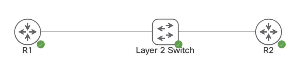
In networking when adding a static route to a router, the static route will make its way into the RIB and FIB if the router can reach the next hop and knows which interface to go out towards its destination. In theory, if the next hop becomes unreachable then the static route is removed from the active routing table until that next hop comes back. This does not work however if there’s an intermediary device in that layer 2 broadcast domain.

On the devices above we have the following interfaces, IPs, and static route.

R1:
Interface IP: 96.76.43.138/29
ip route 150.1.4.4/32 96.76.43.139

R2:
interface IP: 96.76.43.139/29
Interface Loopback0: 150.1.4.4/32

L2 Switch:
Nothing, all layer 2

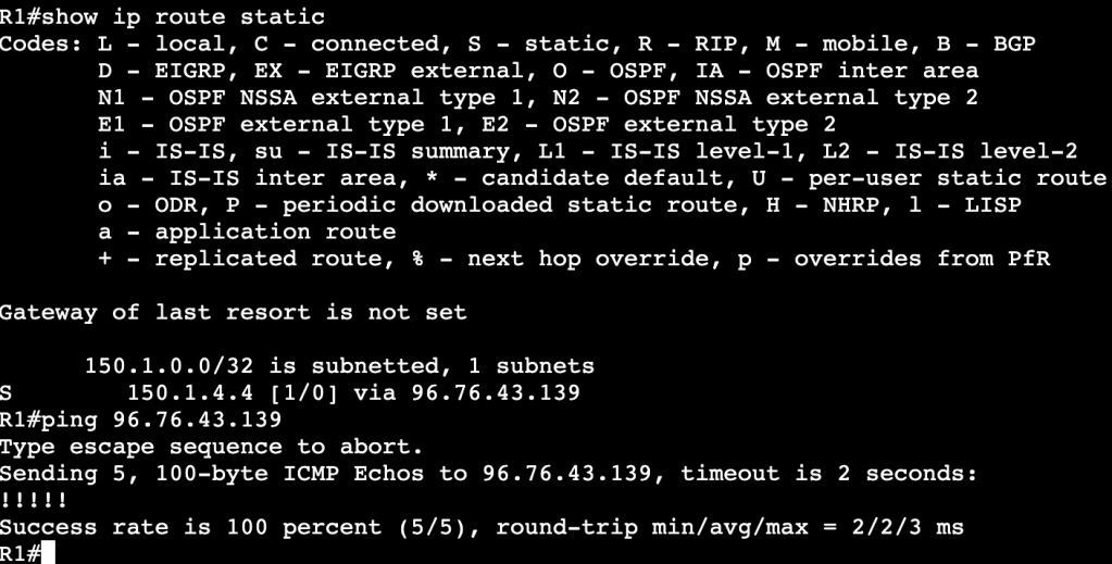
Currently R1’s route table shows the static route is valid and the router can ping R2’s transit interface.

When R2’s interface is set admin down unfortunately R1’s static route does not leave the routing table, even though the next hop is no longer reachable.

This is because the layer 2 device in between is keeping R1’s interface alive. One way of fixing this is with IP SLA. We’ll configure an IP SLA agreement statement that continues to ping R2’s interface, and when the ICMP echo fails, we’ll schedule R1 to remove the static route.

Configuration:

The first part of the simple IP SLA configuration is adding the IP SLA statement with ‘ip sla 1’. It’s using icmp-echo to R2’s transit IP address. And the start time is now with a lifetime of forever. Once this.

Once that’s completed a tracking object needs to be created. The track statement has the number 1 and its associated with IP SLA1. After this is configured a console message will show onscreen saying the the IP SLA has gone from down to up.

The tracking statement needs to now be associated with the static route in R2’s routing table. That can be done with the below command(s):

no ip route 150.1.4.4 255.255.255.255 96.76.43.139 track 1
ip route 150.1.4.4 255.255.255.255 96.76.43.139 track 1

First the old route statement needs to be removed, then the new route with tracking gets enabled.

Below is an image of the route table before R2’s interface is shutdown:

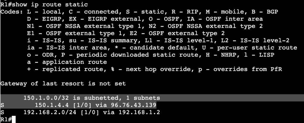
And after R2’s interface is shutdown:

A message above shows the IP SLA 1 state went down. In the route table there is now an entry for the R2 loopback but over another route with a higher administrative distance.

Multiple Spanning-Tree Protocol-802.1Q-2005

  • Removes tie between VLANs and Spanning-Tree instances.
  • Needed when reaching the max limit of VLANs, because the switch will not support that many STP instances.
  • MST Region:
    • Bridges that all agree upon instance name, revision number, and VLAN to STP instance mappings.
    • Intra Region
      • Within Region, details are known.
      • VLAN to STPIs are manually defined.
      • Undefined VLANs fall into CIST/MST0
    • Inter Region
      • Information between regions is not known.
      • Regions see each other as virtual bridges.
      • Simplifies Inter-Region calculation.
      • Intra-Region MSTIs collapsed into CIST.
  • Configuration:
    • Requires Region name, Revision Number, VLAN to instance mapping
    • Enable MST globally.
    • Commands:
      • ‘spanning-tree mst <instance> priority’
      • ‘spanning-tree mst <instance> root <primary/secondary>’
      • ‘show spanning-tree mst <instance>’
      • ‘show spanning-tree root’
      • Enabling:
        • ‘spanning-tree mode mst’
        • ‘spanning-tree mst configuration’
        • ‘name REGION0’
        • ‘instance 1 vlan 1-10’
        • ‘instance 2 vlan 11-20’
    • The root bridge must be in the MST instance, otherwise instance will fail.
  • Backwards Compatibility:
    • When running RSTP or PVST alongside MST, a show spanning-tree will provide ‘Bound’ ports.
  • Ports Gi0/3 and Gi1/0 are connected to a device running PVST. This works though because the root bridge for VLAN 10 is in the MST region.
  • All commands are the same when using RSTP and MST, but instead of using ‘vlan’, we use ‘mst’ and region number/name.

Rapid Spanning-Tree Protocol – 802.1D-2004

  • Differences from legacy STP
    • Rapid convergence due to sync process.
    • Simplifies port states.
    • Additional port roles.
  • Port States:
    • Discarding
      • Drops frames
    • Learning
      • Dropping frames but builds CAM table
    • Forwarding
      • Normal Forwarding
  • Roles:
    • Root/Designated same as legacy STP
    • New:
      • Alternate
        • Same as UplinkFast in regular STP.
        • Upstream interface that’s less desirable to root.
        • No need to configure UplinkFast, just part of RSTP.
        • Immediately begins forwarding upon root port failure.
      • Backup
        • Backup downstream facing interfaces.
        • Activates if primary designated port fails.
        • Normal state is discarding.
        • Only seen in shared segments – ie. hubs.
      • Edge
        • Same as STP PortFast ports.
        • No Topology Changes, immediately begins forwarding.
  • Link Types:
    • Point to Point – Full Duplex
    • Shared – Half Duplex
    • Sync process only occurs on point to point Designated ports.
  • RSTP Sync Process:
    • Process of non-Root Bridge to sync root port with rest of topology.
    • After root port selected, all non-edge ports are considered designated.
    • Bridge then sends out proposals with root bridge info – port costs, etc.
    • Downstream bridges review and either agree or send alternate info.
      • Sending additional info means downstream switch thinks it has better path to root bridge.
    • SYNC PROCESS MAKES SURE ALL RSTP SPEAKERS AGREE ON ROOT PORTS AND DESIGNATED PORTS.
      • Enabling Edge ports is important because it decreases the amount of churn when sync process is occurring. Edge ports do not partake in Syncronization.
  • Failure Detection:
    • In STP, BPDUs are only sent out by Root Bridge
    • In RSTP, BPDUs are generated by every RSTP speaker via Hellos – 2 second default.
    • Reconvergence begins after 3 hellos are missed.
    • MaxAge is used for backwards compatiblity with STP.
  • Convergence:
    • When root port failure occurs, the Alternate port takes over.
      • New root is synced down to all bridges.
    • If no alternate port is available, the bridge declares itself as root bridge, synchronizes, then adapts if there is better info.
    • Slow convergence can happen with large meshy topologies.
  • TCN:
    • Generated after link goes into forwarding state.
    • Originates from switch that detects event.
    • Floods via reverse path forwarding.
    • Causes unicast traffic flooding.

General Spanning-Tree Protocol

  • Order of Operations:
    • Elect the root bridge.
      • After a root bridge has been selected, all of it’s ports will be set into designated ports that are forwarding downstream.
    • Select root bridge interfaces.
      • Each non-root switch will look through ports and elect a root port that is pointed at the root bridge.
      • All other ports will be elected as designated ports that are pointing further downstream.
      • All ports not in designated will be in blocking.
  • Root Bridge Election:
    • Lowest Bridge ID wins.
      • Bridge ID contains:
        • Bridge priority (0-61440)
        • System ID (0-4095)
        • MAC address
  • Changing Root Bridge Election:
    • Change bridge priority manually
      • ‘spanning-tree vlan <vlan id> priority <priority number by 4096>
    • Use root bridge command
      • ‘spanning-tree vlan <vlan id> root <primary or secondary>
      • Will set local priority based on current Root Bridge priority
    • ‘show spanning tree root’ will show which switch is root.
  • Root Port Election:
    • Root Port is upstream pointing towards the Root Bridge.
    • Selected as RP based on lowest path cost (all link costs added up)
      • Higher bandwidth = lower cost – ie. Fa is 19, 1Gbps is 4
      • When a cost tie occurs:
        • Lowest upstream bridge ID
        • Lowest upstream port ID
Port ID under ‘show spanning-tree’ = Prio.Nbr
  • Root Port priority:
    • Per above, lowest wins.
    • Root Port priority can be changed locally, which will then impact the downstream switch.
      • Image above shows root port as Gi1/1 to SW1. If Gi1/1 receives the following config, then the root port is changed to Gi1/2 instead:
        • switch(config-int)#spanning-tree port-priority 240
  • ‘show spanning-tree vlan <id> detail’
    • Will display the local and remote port IDs.
    • Useful for modifying traffic flow in bridging domain.
Can help determine why one port is selected over the other.
  • Changing paths when not changing which switch is Root Bridge.
    • switch(config-int)#spanning-tree vlan <#> cost <#>
      • Command above will change the link cost locally on a switch.
      • By adding all link costs up towards the bridge, we can modify which port is a root bridge locally.
    • Changing paths can be done with the bandwidth command as well.
      • Bandwidth is connected to STP cost.

  • Plain Spanning Tree Protocol timers
    • Hello – How often BPDUs are sent out interfaces.
      • Defaults to 2 seconds
    • MaxAge – How long to wait in blocking without a BPDU
      • Defaults to 20 seconds.
    • Forward Delay – How long to wait in listening and learning
      • Defaults to 15 seconds
  • PortFast
    • Bypasses Forwarding Delay
    • For ports not running spanning tree
    • ‘switch(config-if)#spanning-tree portfast’
  • UplinkFast
    • Legacy for ‘Alternate port’ when root port dies.
    • Automatically switches alternative port to forwarding when root goes down.
    • ‘switch(config)#spanning-tree uplinkfast’
    • Automatically changes all port priorities when root port dies.
      • Way to tell all other switches that it is not the root.
  • BackboneFast
    • Indirect failures should start recalculating immediately.
  • BPDU Filter
    • Filters BPDUs both in and out.
    • Used on Edge ports to transition port to STP speaking member if it receives BPDU.
      • OUT OF EDGE STATE
    • ‘switch(config)#spanning-tree portfast bpdufilter default’
  • BPDU Guard
    • Listens for BPDUs and if it receives one the interface will be put in err-disabled.
    • Can run an err-disabled cause command to bring interface back up after specific interval.
  • Root Guard
    • Shuts ports down if it receives an additional BPDU with better priority.
    • Can be configured with Portfast.
    • switch(config-int)#spanning-tree guard root
  • Loop Guard
    • Prevents unidirectional links by using BPDU keepalives.
    • ‘switch(config)#spanning-tree loopguard default’
    • ‘switch(config-if)#spanning-tree loopguard enable’
  • Unidirectional Link Detection
    • Prevents unidirectional links by using UDLD keepalives.

EtherChannel

Etherchannel:
Logically bonding physical links together.

Consists of Logical interface called port-channel, and physical member interfaces configured to be bundled together.

Hides physical interfaces from upper level protocols like STP.

Individual flows cannot surpass the bandwidth of an individual physical link.

Multichassis Link Aggregation:
Etherchannel spread across multiple switches.

Often used in Cisco Stackwise or vPC.

Two separate switches need to somehow share the Etherchannel control plane.

Static Etherchannel:

  • Supported but not recommended.
    • Failure to properly setup LAG can cause L2 loop.
    • Etherchannel Guard can help mitigate this.

LACP:

  • Link Aggregation Control Protocol
  • IEEE 802.3ad – standard

Configuration:

  • sw1(config-int)#channel-group <#> mode <mode>
  • Modes:
    • ‘on’
      • No negotiation.
      • Dangerous, not recommended
    • ‘active’
      • Initiate LACP negotiation with other side
    • ‘passive’
      • Listen for LACP negotiation from other side

Etherchannel Load Balancing:

  • Methods:
    • Source and Destination MAC address
    • Source and Destination IP Address
    • Source and Destination Layer 4 protocol and/or socket
  • Load Balancing is locally significant.
  • A port-channel between two switches does not need to match load balancing methods on each side.

LB Configuration:

  • Verification that port-channel is up can be done with show etherchannel summary or show int port-channel1 etherchannel:
  • Once verified, load balancing can be changed via ‘port-channel load-balance <method>

Layer 3 Etherchannel:

  • Order of operation matters.
  • When creating routed port-channel interface, do no switchport 1st on physical interfaces, then add them to LAG.