- Standard Access-lists
- Matches on source IP address only
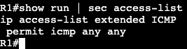
- Extended Access-lists
- match on ip protocol #
- Source and destination address
- protocol options
- tcp/udp ports
- icmp type code
- tcp state (established keyword)
- Packet markings
- DSCP/IPP
- Non-initial fragments (fragments keyword)
- Access-list Logging
- Log can be generated on match.
- Log vs. log-input
- generated as syslog level ‘informational’
- Causes packets to be process switched.
- Logging rate-limiting
- ‘ip access-list logging interval‘
- ‘ip access-list log-update threshold’
- ‘logging rate-limit’
- ACL Syslog Correlation Tags
- ‘log [cookie]’
- ‘ip access-list logging hash-generation’
- Log can be generated on match.
- Applying IPv4 ACL
- Traffic Filtering
- ‘ip access-group’
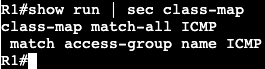
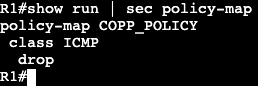
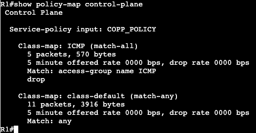
- Traffic Classification
- ‘match access-group’
- Route Filtering
- ‘distribute-list or route-map’
- VTY line/username access-control
- ‘access-class in/out’
- Traffic Filtering

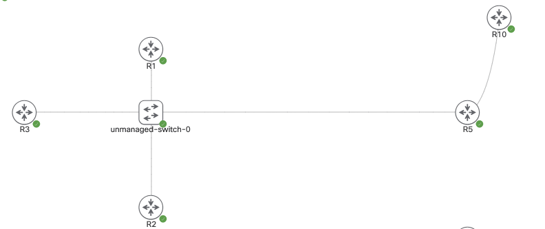
Topology Subnets:
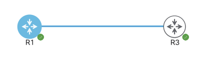
R1: 172.16.1.0/24
SW4: 192.168.1.0/24
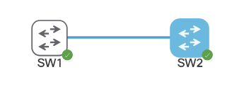
SW2/3/1: 10.30.1.0/24
Access-list Examples:
- On R1 we’ll permit who is allowed to telnet/SSH to the box.

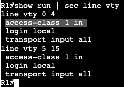
We’re creating an access list and associating it to the VTY lines with ‘access-class’. Can connect successfully from R2, but when trying from R3 I get the following message:

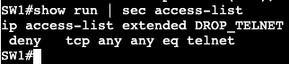
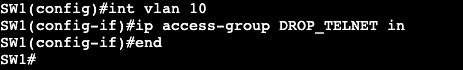
- Now we can get more specific with an extended ACL:
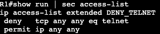

The above will be applied to the interface instead of the VTY lines denying only port 23 from anybody.
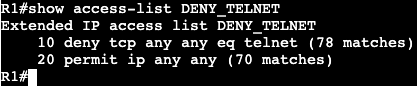
A ‘show access-list’ will confirm the matches of the ACL.
Time Based ACL:
- Used to activate ACL entry based on clock
- Defined as time-range <name>
- Absolute
- one specific time
- Periodic
- One or more recurring times.
- Absolute
- Potential Applications:
- Time based traffic filter
- Time based QoS


- Above is an example of a time based ACL. If the IOS device clock shows between 09:00 and 17:00, then telnet will not be available inbound on the Gig0/0 interface of R1.
Unicast Reverse Path Forwarding:
- Used to simplify Bogon/martian filters
- Addresses that are invalid on the internet.
- Ingress traffic has source checked against CEF table.
- Packets without correct reverse route are dropped.
- Can be both Strict and Loose
- Strict means reverse route must be via ingress interface.
- Loose means reverse route can be via any interface.

URPF can be turned on under the interface. At the end you can specify an ACL that is an exception to the RPF rule.