Blog Feed

Switch ACL

  • Port ACLs
    • Applies to layer 2 switchports
    • Apply ingress only
    • Filter transit traffic.
      • Traffic ingress on the VLAN/port
    • Could be IP or MAC based.
      • MAC ACLs only affect non-IP traffic.
  • Routed ACL
    • Same as PACL but only apply to L3 traffic.
    • Apply to L3 ports or SVIs.
    • Ingress or Egress unlike PACL
    • Can only filter using IPv4 standard/extended ACLs.

Routed ACL example:

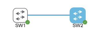
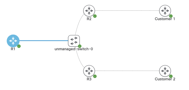
Both switches are running SVI VLAN 10 attached to Gig0/0 as trunk. Each can ping each other’s IP address:

SW1 – 10.10.10.21/16
SW2 – 10.10.10.22/16

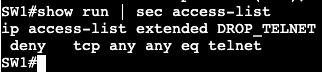
We’re going to apply an extended ACL to SVI VLAN 10 to block telnet traffic that is currently available from SW2 to SW1.

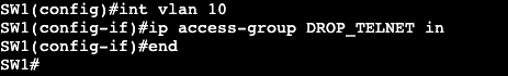
Now if we do a ‘debug ip icmp’ we’ll see that we’re administratively blocked when trying to telnet from R2 to R1.

  • VLAN ACL or VLAN MAP
    • Apply to an SVI
      • Effective for all ports in this VLAN
        • Access and Trunk Ports
      • May inspect both IP and non-IP traffic
        • Matching based on IP or MAC ACL
        • Configuring an IP/MAC entry activates implicit deny.
      • Good for impacting all future ports in VLAN.
      • Don’t use implicit deny
        • May block STP or ARP.
      • Be careful when filtering L2 traffic.
        • STP and ARP could be easily blocked.
      • Account for the fact that ALL transit traffic is affected.
        • Be careful when filtering transit VLANs.

VACL Example:

Now the access-map needs to be applied to VLAN 10.

Note – When doing a VLAN access map, ICMP will not respond saying the traffic was administratively dropped like it does with a normal ACL. It quietly drops the packet.

Control Plane Policing/Protection

  • Control Plane Policing (CoPP)
    • Used to protect CPU from DoS attack.
    • Configured as QoS policing policy.
      • Not all matches supported in class-map
    • Applied under control-plane
      • ‘control-plane’
      • ‘service-policy input’

In this image above both routers are configured with the subnet 192.168.1.0/24, and R3 can ping R1. A CoPP policy below will stop this.

Now under ‘show policy-map control-plane’ we get this:

If we change the policy map to police instead of drop, we can just rate limit how much ICMP traffic is hitting the router control plane.

And now not all traffic is dropped, just rate limited as we can see in the ping above.

Above we can see that there were conformed packets, 33 that exceeded the policing and were dropped.

AAA

  • Authentication, Authorization, and Accounting
    • Old-Model
      • Local Authentication
      • Local authorization based on line/username settings.
    • New-Model
      • Supports AAA lists that define sequence of methods.
      • List can be bound to access technologies.
        • ie. Login or PPP
      • Default lists vs. explicitly assigned lists.
  • TACACS+ & Radius
    • Terminal Access Controller Access-Control System (TACACS)
      • Primarily for device authentication management.
        • ie. IOS admins
      • Supports per-command authorization and accounting
    • Remote Authentication Dial In User Service (RADIUS)
      • Primarily for end user authentication management
        • RAVPN
      • Does not support per-command auth and accounting.
    • Regardless which method used, local fallback should be configured.
  • Local Authentication
    • Default authentication method
    • Passwords are in clear-text by default.
      • service-password encryption
        • Encrypt in running config
      • username secret
Link connecting is 192.168.1.0/24

The image above are two default routers except for the subnet between them. R1 will have local basic user authentication setup with below commands:

Above specifies a local username/password and tells the box to accept the local login for SSH and telnet. From R3 if we telnet we’ll see the privilege level we get from this is privilege 1.

We would need an enable password to get into privilege 15.

Another way of getting in would be using ‘no login’ under the line vty settings. That will get us directly in.

  • Local Command Authorization
    • Privilege levels used to control access to exec commands
    • Default privilege levels
      • 0 – none
      • 1 – user mode
      • 15 – root
    • User Defined Privilege levels
      • Levels 2-14
  • Move command privilege down:
    • Allow privilege 1 to do specific tasks
      • examples
        • run extended pings
        • show running config
          • only see what you can configure.
  • Moving command privilege up
    • Revoke privilege 1 from
      • running show commands
      • using the enable command
  • Local command authorization change:
    • Modified with privilege command
      • exec | configure | interface | router | etc.
    • Configuration mode determines what option of privilege command to do:
      • ex.
        • Exec command
          • router#
        • Configure command
          • router(config)#
        • Interface command
          • router(config-if)#
    • Overhead is a lot for these commands. Better way is RBAC.
  • RBAC
    • Role-based access control
    • Replacement for privilege-levels
      • More flexible in terms of command allocation.
    • Role is a group of commands.
      • Known as parser view
    • Roles could be manualy switched to ‘enable view’
    • Roles could be assigned to users.
    • Roles should be configured from root view ‘enable view’
    • RBAC requires AAA enabled in router.
  • RBAC Configuration:
    • ‘aaa new-model’ must be entered first for this to work.
      • including ‘aaa authentication login default local’
    • Config for a parser view below:

I did not have to enter include commands. They automatically were put in after entering the exclude commands.

Now to enable the view the command ‘enable view first’ must be entered, followed by the password we entered in the original configuration.

Now the commands that show excluded in the output above will not work when logging into the router.

  • Config Change notification and logging
    • Local command accounting
      • tracks users and commands issued through CLI and HTTP
    • Configured as ‘archive’ and ‘log config’.

Now when we do a ‘show archive log config all’, we’ll see my changes:

I logged into the router with the user account cisco, created loopback interface 1 and assigned it the IP address 10.30.1.1/24.

  • Login Enhancements
    • Used to protect against brute force login attacks.
      • After X number of failed attempts, delay login.
    • ‘login block-for’

This will block logins for 10 seconds if there are 3 attempts failed within 60 seconds. It’s a way to slow down brute force login attempts and dictionary attacks.

OSPFv3

  • RFC 5340 – OSPF for IPv6
  • Transport via protocol 89 to unicast and multicasts FF02::5/FF02::6
  • Normal OSPF rules apply
    • Adjacency parameters same
    • OSPFv3 network types same
  • LSAs
    • Two new
      • type 8 (Link) – Used for link local
      • type 9 (Intra Area Prefix) – Used for prefixes on the link
    • Type 8 and 9 separate topology from NLRI
      • v2 has subnet info in LSAs 1 and 2 for Intra
        • if prefix add or remove, run full SPF.
      • v3 uses LSAs 8 and 9 to reference LSA 1
        • If stub network is add or remove, full SPF not required.
  • Configuration
    • Enabled at link level.
      • ‘ipv6 ospf <process id> area <area id>’
      • Automatically enables global process
    • Like EIGRPv6 and BGP, requires IPv4 router id.

The topology above is running DMVPN and we’ll enable OSPFv3. R10 is a normal OSPF broadcast link, and the tunnel interfaces on R1-3 are point to point. R5’s tunnel interface is point-to-multipoint.

On the hub the below commands will be added to the interfaces:

On the DMVPN Tunnel interface the link OSPF command is entered, the network type is changed to point-to-multipoint, and the hello interval is now 10. The timer is changed due to the spokes being point to point.

On the hub’s normal broadcast interface it will receive the normal ipv6 ospf command. This is the same for our normal non-DMVPN router hanging off of R5.

On our spokes each router will enter the following:

Just the normal ospf area 0 command. The timers do not need to be adjusted because the timers already were on the hub. The default OSPF network type on a tunnel interface is point to point, which matches what was changed on the hub.

Notice that on the Hub’s adjacency list, all the neighbors have IPv4 router IDs.

In fact, when trying to form adjacency with the normal router R4, a router ID was manually added to the OSPF process because R4 is only running IP protocol version 6.

OSPFv3 Authentication:

  • Version 3 uses IPSEC for
    • Authentication
      • IPSEC AH or ESP
    • Encryption
      • IPSEC ESP
  • No ISAKMP support, keys manually entered.

Below is an example of the configuration needed on OSPF neighbor interfaces:

This would need to be applied to all tunnel interfaces in the DMVPN topology, as well as the interface connecting R5 to R10.

The long string of numbers and letters are the key that needs to match on both sides of the neighbor relationship. This configuration was found under the Cisco OSPF docs.

Multiprotocol OSPFv3:

  • Can advertise both IPv4 and IPv6.
    • Two separate trees.
      • Each IP protocol runs independently.
    • To advertise IPv4 NLRI, must have both IPv4 and IPv6 on the link.
      • ‘ipv6 enable’ on transit links is min required for v6.
      • For IPv4 – can have all links unnumbered to Loopback interface.
  • Configuration
    • Enable on link
      • ‘ospfv3 <pid> <ipv4|ipv6> area <area #>
    • Options under OSPFv3 routing process.
      • ‘router ospfv3 <pid>’
    • show commands
      • ‘show ospfv3’

IPv6 EIGRP

  • Similar in operation to IPv4 EIGRP.
    • Transport via protocol 88 to unicast and multicast FF02::A
  • Not enabled by default with EIGRP classic mode.
    • ‘no shutdown’ needed under process.
  • Enabled on all IPv6 links in named mode.
    • ‘address-family ipv6 unicast <vrf> autonomous system <#>’
    • process not shutdown by default.
    • To exclude EIGRP link:
      • ‘af-interface Y’
      • ‘shutdown’
  • IPv4 Router-ID needed.

The topology above is running DMVPN Phase 3. R5 is the hub and R1-3 are the spokes. The topology is running IPv4 as the underlay/transport, and then each router has a loopback with IPv4 being advertised into EIGRP AS 1. In addition, each router has an IPv6 address that’s running over the top of IPv4 mGRE/DMVPN. There is no routing protocol yet running IPv6, which is what will be completed with EIGRP.

First step is to turn on EIGRP on each router with the below commands. It will be the same for all:

In addition there was another link added to R5 that is being advertised into EIGRP AS 100. After entering the config above the adjacencies began flapping up and down. Discovered the below command was missing under tunnel 0 on all routers:

Now adjacencies are stable and on spokes we’re seeing a route from the extra link/network coming from R5, outside of the DMVPN domain.

Now on R1 an additional loopback was added with an IPv6 address that’s being advertised into EIGRP AS 100. On R3 when viewing the routing table we’re not seeing it, but we are in R5. This is because split horizon needs to be disabled.

Unfortunately there is a command under the tunnel interface ‘no ipv6 split-horizon eigrp 100’, but it does not work with EIGRP named mode.

R1 Loopback IPv6 2001:15:15::/64

Now R3 is receiving the route from R1’s loopback.

IPv6 DMVPN

  • DMVPN uses IPv4 mGRE for transport.
    • GRE is a multiprotocol encap.
    • Implies IPv6 can be supported.
  • How IPv6 over IPv4 DMVPN works.
    • Build IPv4 underlay and overlay.
      • IPSEC spoke to hub.
    • Use IPv6 NHRP to resolve IPv6 IGP or IPv6 BGP.

The topology above is running DMVPN Phase 3 with EIGRP. R5 is the Hub and R1-3 are the spokes.

The below configurations will add IPv6 over the DMVPN configurations.

Hub:

Spoke 1:

Notes:

  • The hub basically gets an IPv6 address assigned to its tunnel interface, along with the standard NHRP commands. ‘ipv6 nhrp redirect’ is what enables phase 3 on the hub.
  • The spoke needs to get an IPv6 address assigned to its tunnel interface, standard NHRP commands as well. In addition, it needs to map the NHS to the IPv6 address of the hub, as well as mapping the NBMA to the hub’s actual physical transport address assigned to Gig0/0.
  • A ‘show dmvpn’ on the hub displays the DMVPN spokes as well as our IPv6 addresses that are getting tunneled over mGRE. The configuration is IPv6 over IPv4 DMVPN, but we could have used IPv6 as the underlay/transport as well.

IPv6 General Discovery/Addressing

  • RFC 2460 – IPv6
  • Larger address space
    • IPv4 – 32 bit address space
    • IPv6 – 128 bit address space
  • Address Types:
    • Link Local
      • FE80::/10
      • IPv4 equivalent – 169.254.x.x
      • Never routable.
      • Uses:
        • Stateless Address Auto-configuration (SLAAC)
        • Neighbor Discovery
        • Router Discovery
    • Site Local
      • FEC0::/10
      • No one could agree on what a site is.
        • Deprecated in RFC 3879
    • Unique Local
      • Equivalent to RFC 1918
      • ‘Private’
      • Likely unique but not routable over global BGP table.
    • Global Unicast
      • Technically everything else.
        • 2000::/3
      • Per RFC
        • End host must have 64-bit interface ID
        • Use EUI-64 format for interface ID.
    • Modified EUI-64
      • RFC 4291
      • Ethernet MAC to EUI-64 conversion
        • Invert Universal/Local bit
          • 7th most significant
        • Insert padding – 0xFF 0xFE in the middle of address.
    • IPv6 Temporary Addresses
      • RFC 4941
      • MSDN – IPv6 identifiers
        • Randomly generated interface identifiers.
      • Prevents tracking users based on MAC address.
        • EUI-64 result is always the same for a given MAC address.
    • IPv6 Address Resolution
      • RFC 4861
      • ICMPv6 neighbor discovery for layer 3 to layer 2 resolution.
        • Replacement for ARP.
      • Neighbor Solicitation
        • Equivalent to ARP Request.
      • Neighbor Advertisement
        • Equivalent of ARP reply.
      • Router Solicitation
        • Trying to find Gateway.
      • Router Advertisement
        • Use me for routing.

In this image we have R3 and R1 connected via both Gig0/3 interfaces. Interface configs below:

R3
R1

The commands ‘ipv6 enable’ and ‘ipv6 address <address>’ need to be added for unicast routing to work. In addition, the global config command ‘ipv6 unicast-routing’ needs to be entered for IPv6 to function on the box at all.

Once we successfully ping across from R1 to R3, the IPv6 neighbor table will be created. Similar to a ‘show ip arp’ in IPv4.

The table will respond with R3’s link local and global unicast address. Note- this mapping requires ICMPv6 to be enabled. If ICMPv6 is disabled, most IPv6 functionality will break with it.

SLAAC:

  • Automatically assigns IPv6 address for every on-link prefix.
    • Only works with /64s.
    • Duplicate Address Detection (DAD) used to verify uniqueness of generated address.
  • NOT DHCPv6.
    • Does not include router options like DNS.

On router R1 we can add a SLAAC address to the interface gig0/3 with the command ‘ipv6 autoconfig’. That will automatically generate an address which can be seen with a ‘show ipv6 interface gig0/3’.

Within the address the FF:FE is found.

  • SLAAC often works alongside DHCPv6.
    • Options are set in RA messages
    • Tells host there is DHCPv6 server available for addressing options.
  • Other-Config-Flag
    • Use DHCPv6 to receive just addressing options (DNS,TFTP,etc.)
    • ‘ipv6 nd other-config-flag’
  • Managed-Config-Flag
    • Use DHCPv6 for both addressing and options.
    • ‘ipv6 nd managed-config-flag’

Host Default Routing

  • Hosts do not receive gateway from DHCPv6
  • First hop v6 router discovered through Neighbor Discovery and Router Advertisement messages.

IPv6 General Prefix

  • Can be defined to act as shortcut.
    • e.g. if organization is assigned a /32, then all prefixes should be derived from this /32.
    • helps in renumbering scenario.
  • Defined globally as:
    • ‘ipv6 general-prefix <NAME_OF_PREFIX> 2001:123::/32
  • Applied to link as
    • ‘ipv6 address <Name of Prefix> ::1/64
  • General prefix and subnet are merged to derive full address.

Global config command example:

Interface config command example:

The prefix that was added to the interface:

Ultimately a shortcut for assigning prefixes to interfaces.

MPLS and FlexVPN

Above is the topology being setup for MPLS over FlexVPN. The main goal is to have connectivity between Customer 1 and Customer 2.

First steps are configuring FlexVPN on the Hub, R1.

  • Keyring
  • Authorization policy
  • IKEV2 Profile
  • IPSEC Profile
  • Dynamic VTI
  • VRF
  • MP-BGP

Configuration for Spoke 1:

  • Keyring
  • IKEV2 Authorization Policy
  • IKEV2 PROFILE
  • IPSEC Profile
  • Dynamic VTI
  • VRF
NOTE- this VRF is being assigned to Gig0/3 towards the Customer as well.
  • MP-BGP

Configuration for Spoke 2:

  • VRF
NOTE- this VRF is being assigned to Gig0/3 towards the Customer as well.
  • IKEV2 Authorization Policy
  • KEYRING
  • IKEV2 Profile:
  • Dynamic VTI:
  • BGP:

FlexVPN Spoke to Spoke/DMVPN

  • FlexVPN can be setup with NHRP to run a DMVPN type setup.
  • Spokes will communicate directly with each other via NHRP resolution.
    • NHRP Registration does not exist with FlexVPN.

Topology used is below:

Right now it’s a normal hub and spoke topology with FlexVPN. All router loopbacks are being advertised over IKEV2. R1 has a virtual template setup.

To enable spoke to spoke communication, we’ll need to enable NHRP under the Virtual-Template interface. This cannot be completed however if there’s an active VPN tunnel running over the interface. Removing the SA requires shutting down the interface R1 is connected to. The SA does not completely leave the box for a few minutes after.

Under the Virtual-Template interface on our hub we’ll add the two NHRP commands with a network-id of 1. Then on the spokes a dynamic VTI is required for spoke to spoke communication. This will require a Virtual-Template as well using ip unnumbered Tunnel #.

In addition the NHRP commands need to be added to the existing static VTI.

When spoke to spoke communication is needed, both spoke routers will need to authenticate with each other. That will require using the existing keyring.

All of the above will need to be configured for additional spokes. The same has been applied to R3, but with peer IPs that work.

List

  • The following was configured:
    • NHRP Redirect and network-id under Hub Virtual-Template
    • A Virtual-Template Interface on each spoke with the following:
      • IP Unnumbered
      • NHRP ID and shortcut <‘virtual-template #’>
      • Tunnel source
      • IPSEC profile
    • New Peer under Keyring
    • NHRP Network ID and Shortcut under Tunnel 0

Now when looking at the route table of our hub, we’ll see the following static routes associated with Virtual-Access interfaces.

On the spokes we’ll see initially only static routes for the hub loopback. If we run a ping from spoke to spoke though, we’ll see that R2 will receive override routes once the NHRP redirect process has completed.

In addition our virtual access interface(s) will go up when the spoke to spoke tunnel is functioning.

FlexVPN – Hub/Spoke

The topology above is going to setup a DMVPN type scenario but it’s going to run FlexVPN. The shared subnet the three routers are connected to is 10.30.1.0/29.

R1: Loopback 1 – 172.16.1.254
R2: Loopback 2 – 2.2.2.2/32
R3: Loopback3 – 3.3.3.3/32

Hub:

  • Keyring
    • Using quad 0 for remote addresses (any)
    • Same PSK across the board.
  • AAA authorization settings (IKEv2 Routing)(‘aaa new-model’)
    • Using routing via IKEv2
    • Requires access list which is any.
  • IKEv2 Profile
    • Identity for simplicity is ‘any’
  • IPSEC Profile
    • IPSEC profile that specifies the IKEv2 profile
  • Virtual-Template
    • The virtual template is a virtual interface, but the IP address cannot be applied directly to it. It requires unnumbered with the loopback interface we’re connecting to each spoke with.

Spoke:

  • Keyring
  • Authorization Policy
  • IKEv2 Profile
  • IPSEC Profile
  • Static VTI
    • Note there is no virtual template on the spokes, just the hub.
  • Verify
    • ‘show crypto ikev2 sa’
    • ‘show crypto ipsec sa’