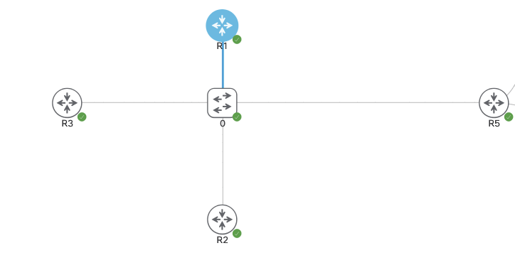
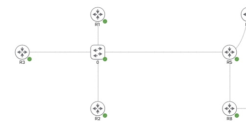
The below topology is running DMVPN Phase 3. R1-3 are spokes and R5 is the hub. Currently the routers are all running IPSEC via IKEv1 and we’re going to change this to IKEv2.
IKEv1 vs. IKEv2 (out of scope for CCIE)
IKEv2 can use asymmetric authentication.
ie. one side running PSK and other running PKI.
IKEv1 has to be the same on both.
By removing the line ‘no tunnel protection ipsec profile vpnprof‘we’re able to remove IPSEC IKEv1 from each tunnel interface. The IKEv1 configuration will still be on the box but not applied to anything.
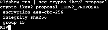
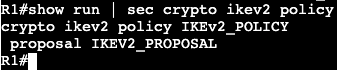
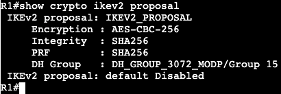
The configuration for IKEv2 will be the following:
IPSEC with IKEv1 configuration is going to leverage the topology/lab that’s already setup with plain DMVPN mGRE.
The configuration is already setup with BGP and R5 as the hub. The below configuration will be the same on every router and it will add IPSEC encryption over each tunnel.
In the same topology above will be running DMVPN with BGP this time. Currently there are no routing protocols setup, only the DMVPN phase 3 configs. R1-3 are spokes and R5 is the hub.
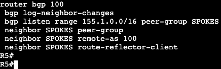
BGP in DMVPN is able to leverage BGP Peer Groups. We setup a group name associated with an IP range that is able to automatically be added as a BGP neighbor, then we assign that peer group desired BGP neighbor parameters. The config on the hub is below.
All of this is running iBGP/ASN 100. A spoke configuration is below.
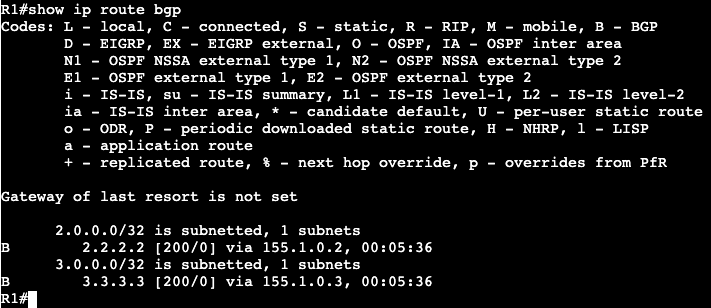
This can be applied to all spokes. After this is entered all neighbors come up and a spoke routing table looks like below:
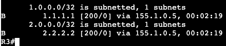
Note that the next hops are preserved instead of being modified by the hub. From spoke 2 to spoke 1 we’re going to run a ping and let the direct tunnel form. After we’re getting the following on R2:
R2 is receiving an ‘H’/NHRP route and we can see the tunnel formed directly between the two spokes.
On R5/Hub we can change the behavior of the next hop by enabling next hop self.
Now the route table on a spoke has the next hop setup as the hub itself.
BGP Summary:
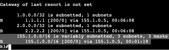
Similar to EIGRP, BGP allows us to summarize prefixes from any location. On the hub we’re going to summarize our transit/VPN range – 155.1.0.0/16.
After a ‘clear ip bgp * out’ on the hub, we begin seeing the summary address above on spokes.
Now from R1 we’ll ping R3 and let the dynamic tunnel come up. Again in the routing table we’re seeing the ‘%’ override symbol and an NHRP ‘H’ route.
A Default route can be setup instead of the summary address on the hub as well. In BGP we’re going to remove the aggregate address and add a default originate command.
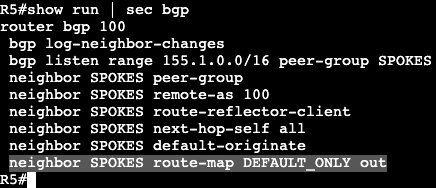
R5 is now advertising a default route AND all the specific routes. If we want to make this ONLY default route from R5 to the spokes, we can do that with a route-map/prefix list combination.
Then apply the route-map outbound to the neighbor group in BGP.
This now pushes only 0.0.0.0/0 from R5 to the spokes.
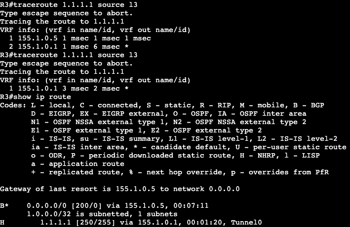
Now when trying to establish spoke to spoke connectivity, NHRP will kick in and create a more direct route as traffic is needed.
Above R3 is running a trace to R1 and it initially shows hitting the DMVPN Hub at .5. The second attempt at the trace shows R3 going directly to R1. Once the dynamic tunnel is stood up we see that the NHRP route has been added to R3’s route table.
The advantage of BGP in a DMVPN topology is that you can be very specific on what routes you are advertising from hub to spoke. In addition, the BGP listen feature can be used for easier spoke turn up.
Sends NHRP redirect message back to packet source.
Forwards original packet down to spoke via RIB.
Routing
Summarization/default routing to hub allowed.
Results in NHRP routes for spoke to spoke tunnel.
With no-summary, NHO performed for spoke to spoke tunnel.
next hop is changed from hub IP to spoke IP.
Next hop on spokes is always changed by the hub.
Because of this, NHRP resolution is triggered by hub.
Multi-level hierarchy works without daisy-chaining.
Configuration:
The topology currently is the one above, R1-R3 are DMVPN Phase 2 spokes and R5 is the hub. Each router is running OSPF over its tunnel 0 and advertising the loopback.
R5/Hub: Physical IP – Gig0/0 – 96.76.43.137/29 VPN/Tunnel IP – Tu0 – 155.1.0.5 Loopback – L5 – 5.5.5.5/32
R1/Spoke: Physical IP – Gig0/0 – 96.76.43.140/29 VPN/Tunnel IP – Tu0 – 155.1.0.1 Loopback – L1 – 1.1.1.1/32
R2/Spoke: Physical IP – Gig0/0 – 96.76.43.138/29 VPN/Tunnel IP – Tu0 – 155.1.0.2 Loopback – L2 – 2.2.2.2/32
R3/Spoke: Physical IP – Gig0/0 – 96.76.43.137/29 VPN/Tunnel IP – Tu0 – 155.1.0.3 Loopback – L3 – 3.3.3.3/32
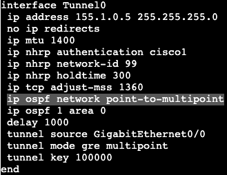
The OSPF network types are currently set to Broadcast with the hub as DR. If the network type on each tunnel interface is changed to ‘point-to-multipoint’, we’ll see that the DR/BDR process goes away.
Network type adjusted on all spokes as well as hub.
Now on a spoke if the routing table is shown, we’ll see that each spoke next hop hits the hub, unlike the broadcast network before. This is due to Next Hop Override not functioning yet.
To enable NHO, we need to add some commands. On each spoke we’ll add ‘ip nhrp shortcut’, and the hub gets ‘ip nhrp redirect’. Both of these commands are added on the tunnel 0 interface, or in general the DMVPN tunnel interfaces.
Now when doing a traceroute from R1 to R2 you can see that traffic first gets directed to the hub, then down to R2/spoke. If the traceroute is performed again though we’ll see the traffic goes directly from spoke to spoke.
Looking at the routing table of R1 shows now a % sign next to the route on R1 to R2 – 2.2.2.2, which means next hop override is taking place. Next hop does not change in the routing table but it can be seen in the cef table.
EIGRP:
OSPF has pretty big limitations in this type of topology when it comes to route manipulation via areas and summarization. If a tool like summarization were to be used, it’s much better to use BGP or EIGRP.
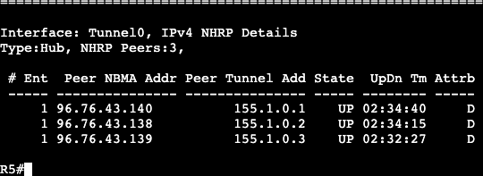
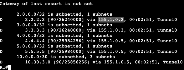
The above topology was changed to run EIGRP. We’re enabling all the same interfaces in the EIGRP process and there are three EIGRP DMVPN neighbors on the hub. Each spoke is receiving routes over the DMVPN tunnels.
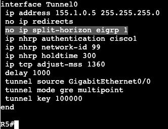
In the image directly above we’re reading the routing table for R1. Notice that it’s only receiving routes from the hub at R5. None of the routes from our other spokes, R2 and R3. That’s because the hub needs the command ‘no ip split-horizon eigrp 1’.
Once that’s added R1 begins receiving the routes from the other DMVPN spokes. The next hop does not change in Phase 3 however, that’s still the default behavior. In Phase 2 we’d add Next-Hop-Self, but that’s unnecessary in Phase 3 due to NHRP’s response that advises spokes to enable direct tunnels to each other.
With EIGRP enabled we can run a traceroute from R1 to R2 and we’ll see the first packet gets directed to the hub, R5. Running a traceroute again will show traffic is now going directly from spoke to spoke. In the routing table of R1 we’ll see that there’s a NHO occuring from the ‘%’, and in the cef table we’ll see that this is where that NHO is taking place.
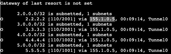
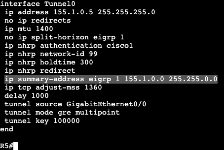
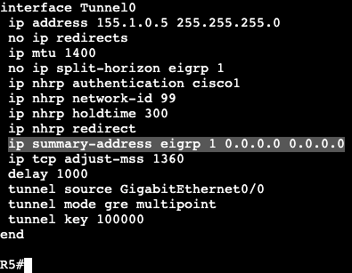
Now because this is EIGRP, we can easily do a summarization from the hub. On R5 we’ll enter the below commands and then look at a spoke routing table.
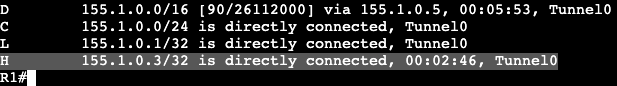
R1 Route Table:
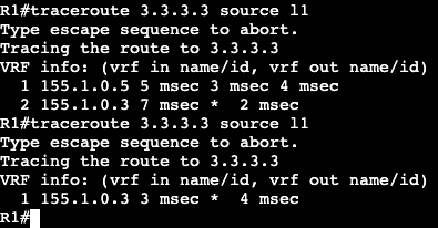
Now from R1 a traceroute will be performed from R1’s loopback to R3’s loopback.
First try the packet hits the hub first. Second try it goes directly over the dynamic tunnel.
Now in the routing table of R1 a route labeled ‘H’ is visible, which means it’s from NHRP. When using summarization in DMVPN, NHRP will take care of the more specific routes when they’re needed – ie. when traffic is actually going from spoke to spoke.
Default Route:
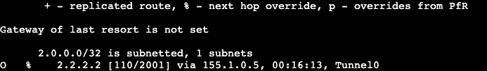
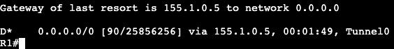
This summarization can be done with a single default route as well. On the hub the summary address has been removed and a 0.0.0.0 0.0.0.0 has been added.
On a spoke the ‘show ip route eigrp’ now looks like below:
After pinging R2 (spoke) and looking at R1’s routing table again, we’ll see that NHRP has added another more specific route in our DMVPN topology.
In the image above we are setting up DMVPN phase 2. R1-3 are spokes and R5 is the hub. Current reachability should not matter all that much because it’s one broadcast domain between the four routers. IP addresses are assigned below:
R5/Hub: Physical IP – Gig0/0 – 96.76.43.137/29 VPN/Tunnel IP – Tu0 – 155.1.0.5 Loopback – L5 – 5.5.5.5/32
R1/Spoke: Physical IP – Gig0/0 – 96.76.43.140/29 VPN/Tunnel IP – Tu0 – 155.1.0.1 Loopback – L1 – 1.1.1.1/32
R2/Spoke: Physical IP – Gig0/0 – 96.76.43.138/29 VPN/Tunnel IP – Tu0 – 155.1.0.2 Loopback – L2 – 2.2.2.2/32
R3/Spoke: Physical IP – Gig0/0 – 96.76.43.137/29 VPN/Tunnel IP – Tu0 – 155.1.0.3 Loopback – L3 – 3.3.3.3/32
The config on the hub/R5 is below:
The config on any spoke is below, minor IP changes:
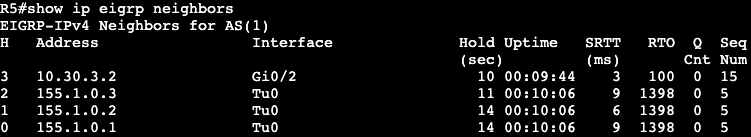
On each router we’re running EIGRP AS 1 that is advertising each loopback and participating/creating adjacency on the physical interface. The main difference between the hub vs. spoke configuration are the NHS, map and map multicast commands. All of them specifying the hub/server/hub IPs.
Now on the hub we’ll see the below screen after entering ‘show dmvpn’:
The attribute D on the right means they were setup dynamically. Now looking at routes sourced from EIGRP, we receive the following from a spoke:
R1 is receiving the loopback of R5, as well as a couple routes from a router running EIGRP on the other side (outside of DMVPN) of R5. A router advertising it’s own loopback of 4.4.4.4/32.
Unfortunately we are not receiving routes from the other DMVPN spokes. This is due to EIGRP being a (hybrid) distance vector protocol that uses Split Horizon as loop avoidance. To fix this the hub will need to turn split horizon off.
After this there is a DUAL resync and the routes start to come through.
Spoke to Spoke communication:
As of right now if a spoke wants to speak to another spoke, it will first have to traverse the hub. This is due to EIGRP changing the next hop value to its tunnel 0 interface. This can be changed with the command below on R5 tun0:
‘no ip next-hop-self eigrp <process id>‘
Now the routes on R1 show the VPN address of each spoke as the next hop. If a traceroute is completed from R1’s loopback to R2’s loopback, the first hop shows it goes to the hub, second to the spoke. If this is performed again however it can be seen that now there’s spoke to spoke communication. In addition on R1 we’ll see with ‘show dmvpn’ that there’s a dynamic tunnel created between the two.
OSPF:
All of this can be completed with other routing protocols. EIGRP has been removed from each router and now this will be completed with OSPF.
For the spokes on each tunnel and loopback interface we’re going to enable ‘ip ospf 1 area 0’, and on the tunnel interface we will change the network type via ‘ip ospf network broadcast’.
The two commands above will be added on the hub as well, but the hub also needs the command ‘ip ospf priority 255’ under the tunnel interface. The reason for this is because we cannot have any non-hub device as the Designated Router. If a spoke becomes the DR then updates will not work because each spoke does not statically have a connection between the two devices. The hub is needed for the DMVPN spoke to spoke connectivity. Routing updates in this situation will eventually fail.
An additional command to make sure a spoke does not become the DR is by changing their priority to 0 so they take themselves out of the election process.
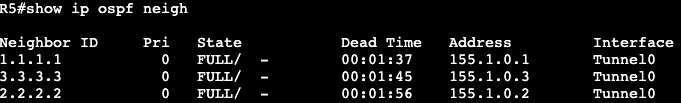
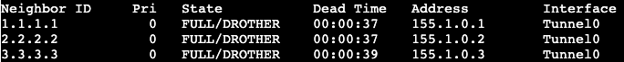
An‘ip ospf priority 0’ shows that all of the spoke neighbors are now DROTHERs, so they’ll never even be a BDR.
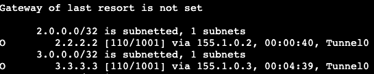
Now on R1 when looking at ‘show ip route ospf’ we’ll see the routes for the neighbors come in. On the routes to other DMVPN spokes, we’ll see that the next hop is not modified like it was originally in EIGRP.
To reach 3.3.3.3, the next hop value is the VPN address of R3 instead of R5, the hub. This is why OSPF Broadcast network type is used. The DR process does not modify next hop. The limitation to using OSPF in DMVPN however has to do with needing to specify DR and not being able to summarize. In this scenario all routers are in area 0.