Blog Feed

Layer 2 Multicast

  • Ethernet Multicasting
    • Supports L2 multicast natively.
      • Multicast bit in 48-bit address: lowest bit in the first byte.
      • Anything that starts with 01-
    • Multicast addresses used for various purposes.
      • CDP, L2 protocol tunneling.
      • Allocated by IEEE.
    • IPv4 addresses map to MAC to forward on LAN
      • Allows L2 switches to forward multicast intelligently.
    • MAC address range
      • 01-00-5E-00-00-00 to 01-00-5E-7F-FF-FF
        • First 25 bits fixed
        • Last 23 bits mapped from IPv4 address.
    • Implies overlap of addresses.
  • Switches treat unknown unicast and multicast like broadcast
    • Multicast traffic flooded out all ports in broadcast domain.
    • IGMP Snooping needs to be used to avoid this.
  • IGMP Snooping:
    • Switch listens for IGMP Report/Leaves
      • L2 device inspects L3 frames.
      • Extracts group address reported.
      • Prunes unneeded Multicast
    • Multicast Routers have to be discovered
      • Routers need to process all multicast traffic.
      • Switch listens to PIM messages.
        • PIM Snooping

Configuration:

  • ‘ip igmp snooping’
  • ‘ip igmp snooping vlan x’
  • Statically assign port to group:
    • ‘ip igmp snooping vlan <x> static <ip> interface <interface>

  • IGMP Snooping and STP
    • STP TCN may signal receiver moving.
      • After TCN event switch floods all multicast groups out all ports.
      • ‘ip igmp snooping tcn flood query count <count>’
      • Above command means flood until <count> query intervals have expired.
    • Disabling flooding during TCN
      • ‘no ip igmp snooping tcn flood’
  • IGMP Profiles:
    • access-group only on L3 interfaces.
    • Profile allows IGMP access-control at Layer 2.
      • Profiles are either in permit or deny mode.
      • Permit mode allows specified groups and blocks all others.
      • Deny mode blocks specified groups and allows all others.
      • Configuration:
        • ip igmp profile 1
        • permit
        • range 239.0.0.0
        • range 237.0.0.0 238.0.0.0
        • int gig1/0/45
          • ip igmp profile 1
  • IGMP Throttling
    • Limits amount of groups joined on interface
      • ip igmp max-groups NN
      • ip igmp max-groups action <deny|replace>
        • New groups are either denied or replace old ones.

Bidirectional PIM

  • RFC 5015
  • Traditional Sparse Mode forms two trees.
    • Unidirectional SPT from source to RP
    • Undirectional shared tree from RP to receivers.
  • Results in (*,G) and (S,G) control plane.
    • Doesn’t scale well.
  • Bidirectional PIM solves this by only allowing the Shared Tree (*,G) and never a SPT (S,G).
  • Operations:
    • Define an RP and group range as bidirectional.
      • Stops formation of (S,G) for range.
    • Build single (*,G) tree towards RP
      • Traffic flows upstream from source to RP
      • Traffic flows downstream from R to receivers
    • Removes PIM Register process
      • Traffic from sources always flow to RP.
    • Uses Designated Forwarder for loop prevention.
  • Bidir Designated Forwarder:
    • One DF is elected per PIM segment
      • Lowest metric to RP wins.
      • Highest IP in tie.
    • Only DF can forward traffic upstream towards RP.
    • All other interfaces in OIL are downstream facing.
    • Removes the need for RPF check.
      • Due to this all routers must agree on Bidir or loops can occur.

Configuration:

In this topology we’re going to setup R1 as the Rendezvous Point.

Bidirectional PIM first needs to be enabled globally, and then added on to the rp-address command. This needs to get turned on for every router in the path.

Now on R8 we’re going to join a group.

After the group Join reached the RP, R1 now sees the receiver/(*,G).

We’re going to now setup a continuous ping on R9 to the group address and see what the mroute shows on R1.

Which is still only showing the (*,G) because this is Bidirectional PIM. The full SPT does not exist, will not form.

Entire goal is to reduce the number of senders in the Multicast Table.

Source Specific Multicast (SSM)

  • Any Source Multicast (ASM)
    • Traditional PIM Sparse Mode with an RP.
    • Receiver does not yet know who the sender is.
    • Sender and Receiver are connected through the RP.
    • Both (S,G) and (*,G)
    • Source begins to send traffic.
      • PIM DR hears app feed (S,G)
      • Unicast PIM Register is sent from DR to RP.
      • RP acks DR with Register Stop.
      • RP now knows about (S,G)
    • Receiver signals group membership
      • App sends IGMPv1/2 Report for (*,G)
      • IGMP Querier translates to (*,G) PIM Join towards RP
      • PIM Join forwarded up RPF path to RP
      • RP now knows about receiver.
    • RP joins (S,G)
      • RP sends (S,G) PIM Join up RPF path to source.
      • App now flows from source to RP.
    • RP forwards to receiver via (*,G)
      • Receiver now gets app flow.
    • SPT Switchover
      • Last hop sends PIM join (S,G)
      • Last hop sends PIM Prune (*,G)
      • Receiver is now joined to the (S,G)
    • Issues with ASM Design
      • Receivers don’t know about senders in advance.
        • RP is used to find senders.
      • RP is a bottleneck in the control plane.
        • RP failure means that new trees can’t be built.
        • RP is at least temporarily in the data plane.
      • Solution
        • Have receiver pre-learn the source out of band.

  • Source Specific Multicast (SSM)
    • Group address range 232.0.0.0/8
  • Receiver knows app source before it signals membership.
    • Receiver uses IGMPv3 Report to signal (S,G) join.
  • RP is not needed to build the shared tree.
    • App already knows source.
    • RP not needed to build control plane.
  • Result is only (S,G) trees
    • Last hp router sends (S,G) PIM Join up RPF towards source
    • Each tree is SPT for (S,G)

Configuration:

  • Enable multicast routing
    • ‘ip multicast-routing’
  • Define global SSM Group range
    • ‘ip pim ssm <default|range>
  • Enable PIM Sparse at interface level
    • ‘ip pim sparse-mode’
  • Enable IGMPv3 on links to receivers
    • ‘ip igmp version 3’

In the below topology we’re going to setup SSM. R9 we’re going to start with sending a ping to 232.1.1.1, which should fail right away because there is zero configuration for that group.

On the other side of the topology we’re going to run a source specific join from R8. First step is enabling IGMPv3 on the link towards the source, which is also towards R10.

That is completed on both R10 and R8 because the first hop router will be sending the Join message.

In addition, SSM default needs to be turned on for every single router in the path.

Now, on R8 we’re going to continue joining the group. The command is similar to IGMPv2 but now specifies the source, which is 9.9.9.1.

After entering the join, the extended ping from our source R9 begins to receive responses.

Now when doing a ‘show ip mroute’ on R4, a router in the source to destination path, we only see the (S,G) and no (*,G).

Multicast Anycast RP and MSDP

  • Anycast
    • One to nearest routing.
    • Multiple destinations share same address.
    • Route to closest one based on routing protocol.
    • Poor man’s load balancing and HA.
  • Anycast Operations:
    • Mirrors application data to multiple devices in topology.
    • Assign each device the same duplicate IP and advertise it
      • Same /32 Loopback into routing protocol.
    • Use the routing table for load balancing and HA.
      • Routing to specific destination depends on where you are physically in the topology.
      • If anycast device fails, use routing convergence to find the next closest device.
  • Anycast RP
    • Uses Anycast load balancing to decentralize placement of PIM Sparse Mode RPs.
      • PIM Register and Join messages go to closest RP in topology.
      • If one RP goes down, convergence is up to IGP.
      • As long as one anycast RP is up, new trees can be built.
      • RP failure does not necessarily impact current trees.
    • Design Issues:
      • Requires all RPs to share information about senders and receivers.
        • MSDP helps with this.
  • Multicast Source Discovery Protocol (MSDP)
    • Used to advertise (S,G) pairs between RPs.
      • Listen for PIM Registers regarding (S,G)
      • Tell other RPs about (S,G) through an MSDP Source Active (SA) message.
      • Essentially like an inter-RP PIM Register message.
    • Allows PIM domains to use independent RPs
      • Originally designed for Inter-AS Multicast
      • CCIE Use Case is Anycast RP for Intra-AS Multicast.
  • Setup:
    • Anycast RPs assign duplicate Loopback address and advertise into IGP.
    • All routers point to anycast RP address.
      • Can be static or dynamic assignment.
    • Anycast RPs are MSDP peers using a unique address.
      • Each device has a globally routable Loopback plus the Anycast Loopback.
      • If three or more RPs, usually a mesh group.
    • When PIM Register is received, MSDP SA is sent to MSDP peers.
      • Results in sync of (S,G) information.
      • RP that knows about receiver can now join the (S,G) tree.
  • Caveats:
    • Requires duplicate addresses
      • Ensure control plane protocols don’t use duplicate IP as identifier
        • ie. router-id
    • Requires unique address to sync the application data
      • App is hosted on Anycast
      • App data sync between Anycast peers needs to be routable (unique).
        • Similar to VIP in HA pairs, etc.

Configuration:

The image above is the topology being worked on. Every router has ip multicast enabled, is running OSPF in area 0, and is advertising unique loopbacks/addresses into OSPF. There are no IGMP groups currently running, but PIM is enabled on each transit interface.

The two routers that will be performing Anycast and acting as Rendezvous Point (RP) are R6 and R4. On each router we’ll create Loopback interface 20 and give the interface an IP of 20.20.20.20. That interface will join the OSPF process with ‘ip ospf 1 area 0’

After advertising the loopbacks into OSPF, R1, the router in the middle, now has two destinations to 20.20.20.20/32. R6 and R4.

Next step is to have all the routers in the topology pointing to 20.20.20.20 for their PIM RP mapping. This command will be applied to all routers.

Now to verify the routers are using 20.20.20.20 as their RP, the command is run below.

Now we’ll add a group into the mix. On R8 we’ll do an IGMP join then take a look at the mroute tables.

R4 Normal
R6 No Group

On R4 everything is behaving normally. The RP found the listener and is waiting for a sender to complete the SPT. On R6 however, the group is not found because the two RPs are not syncing data with each other.

If I go over to R9 on the other side of the topology and ping 127.0.0.1, the two RP mroutes for this group will appear like below:

R6 shows it created the full tree, but it has an outgoing interface of Null. This is because it has no idea about where the listener/receiver is located.

R4 shows it only has the listener/receiver location and no idea where the source would be.

Below are the commands to enable MSDP.

On R6 we’re peering with R4 at 4.4.4.1, and on R4 we’re peering with R6 at 6.6.6.1. Note the peering needs to happen on unique addresses, cannot use the Anycast address.

After the commands are entered we get a session up message in the terminal. Now when pinging from R9 to 227.0.0.1 I’m getting responses and the mroute tables look like this on the two RPs:

R4 (S,G)
R6 (S,G)

When R9 begins pinging 227.0.0.1, R6 receives a PIM Register message that gets passed on to its peer R4 via MSDP Source Active (SA).

Bootstrap Router

  • RFC 5059
    • Similar functionality to Cisco proprietary Auto RP.
  • Roles
    • RP Candidate
      • Similar to Candidate RP
      • Uses Unicast PIM to advertise itself to Bootstrap Router
    • Bootstrap Router
      • Analogous to mapping agent
      • Advertises RP info to other routers with multicast PIM on a hop by hop basis.
  • By default Auto-RP and BSR messages are sent on all PIM enabled interfaces.
  • For added security, these messages should be filtered on network edge.
    • Auto-RP via Multicast Boundary
    • BSR via BSR Border
  • Filtering can occur via TTL as well.
    • ‘Administrative Scoping’

Configuration:

In the topology above all routers are running OSPF in area 0. They each have ip multicast enabled and we’re going to make R1 the RP via BSR.

The first two commands above will make R1 the BSR and RP Candidate. The ‘group-list 1’ is referring to an access-list numbered 1 that allows the below Multicast addresses to report into the RP.

An RP Mapping will show the same prefixes:

On R9 we can confirm that R1 is now officially the RP of the Multicast domain.

Now on R8 we’re going to create a PIM Join to the group 239.0.1.1 and and check the mroute table on R1. R8: ‘R8(config)#ip igmp join-group 239.0.1.1’

R1 now has the group setup in a (*, 239.0.1.1), meaning it not yet has a sender but knows which interface to go out for receivers/group members.

After hopping onto R9 and trying to ping the group address, R1’s mroute table looks like below:

It now has the full SPT tree completed with an (S,G) – (10.30.8.2, 239.0.1.1)

NOTE:

Command ‘show ip pim rp’ will show RP for all Multicast groups.

Auto RP

  • PIM Sparse mode
    • Traffic not flooded unless asked for it.
    • Uses RP as root of Shared Tree
    • PIM DR hears sender and reports (S,G) to RP through PIM Register
    • Last hop router hears IGMP Join and sends (*,G) PIM join towards RP.
    • RP sends (S,G) PIM join towards source to complete shared tree.
    • Last hop router can initiate PIM SPT Join and Shared Tree Prune once feed is end-to-end.
  • Without RP
    • Sources cannot register
    • Joins cannot be processed
  • All routers must agree on same RP address on a per-group basis
    • Registers and Joins are rejected for invalid RP.
  • RP address assignment.
    • Can be done statically or Dynamically.
    • Dynamically
      • Auto-RP
      • BSR

Auto RP:

  • Cisco properietary
    • Two functional roles
      • Candidate RP
        • Devices willing to be the RP
      • Mapping Agent
        • Chooses the RP among candidates and relays this info to the rest of PIM domain.
    • Allows for redundancy of RPs

Auto RP Process:

  • Candidate RP sends announcement with group range they are willing to service.
    • Uses group (S, 224.0.1.39)
  • Mapping agent then discovers candidate RP and advertises their mappings to all other routers
    • Joins (*, 224.0.1.39) to discover about Candidate RPs
    • Announces final RP advertisement with (S, 224.0.1.40)
  • Caveats:
    • Dynamically learned RP mapping preferred over static.
    • Auto-RP control plane messages are subject to RPF check.
    • Routers must join (*, 224.0.1.39) for Candidate RP and (*, 224.0.1.40) for mapping agent.
    • Pim Sparse Mode
      • Cannot join the Auto-RP groups without knowing where the RP is located.
      • Cannot know where the RP is without joining the Auto-RP groups.
      • Recursive Logic.
      • Solutions:
        • Default RP Assignment
          • Assign static RP for groups for 224.0.1.39 and .40.
          • Defeats purpose of dynamic.
        • PIM Sparse-Dense Mode
          • Dense for groups without an RP
          • Sparse for all others.
        • Auto-RP Listener feature
          • Dense for 224.0.1.39 and .40 only
          • Sparse for others.
  • Auto-RP with multiple candidates.
    • For redundancy and load distribution, Candidate RPs can be configured.
    • ACL applied on Candidate RP controls what groups they service.
    • If multiple overlapping Canddiate RPs, Mapping Agent chooses highest RP address.
  • Mapping Agent Security
    • Needs to be protected against false RP Candidate RP advertisements.
    • RP Announce Filter feature can permit or deny Candidate RP to be accepted.

Auto-RP Configuration:

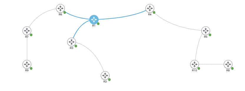
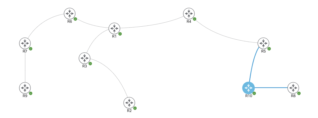
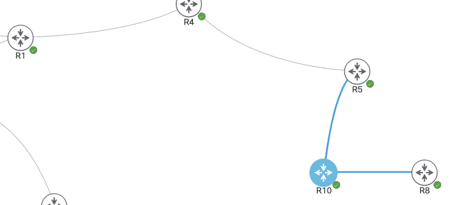
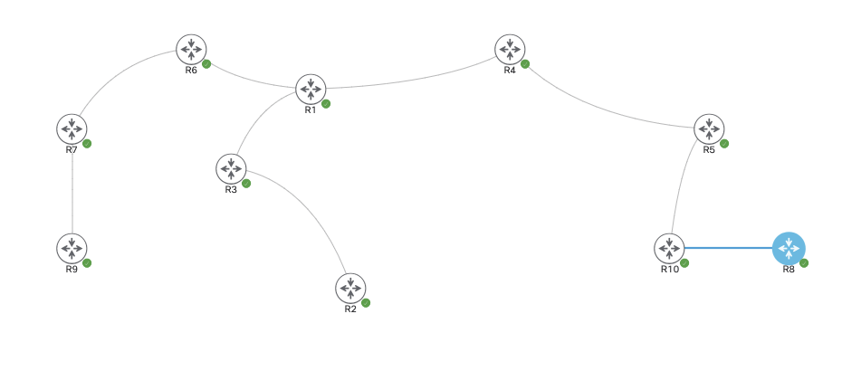
In the above topology we’re running OSPF on all routers in Area 0. They’re each advertising a loopback address into the domain and each have Multicast enabled. There is however zero RP at the moment. To enable Auto-RP we’ll first add the autorp listener command to each device.

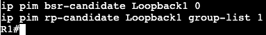
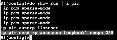
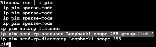
In this environment the router R1 will become the RP. On R1 we’ll first need to allow the router to send RP announcements. We’ll be sending these announcements out via interface Loopback1 and the scope will be a TTL of 255.

And for the mapping agent we’ll need to add in the RP discovery for the mapping agent. Again the interface used will be interface Loopback1 and the TTL of 255

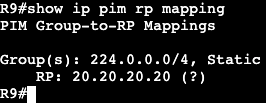
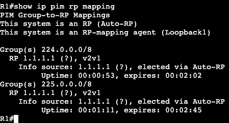
Shortly after once doing an ‘show ip pim rp mapping’ you can see that this host is now the Auto RP and mapping agent.

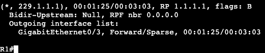
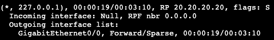
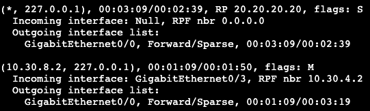
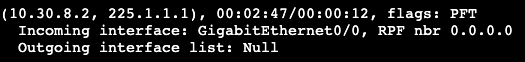
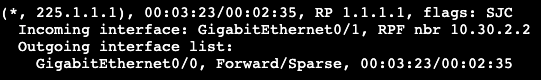
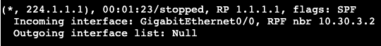
Now, if we head over to R9 and ping the group 225.1.1.1, the RP at R1 will have an (S, G) in its mroute table for 225.1.1.1 with the router I just pinged from.

The incoming interface is the unicast outbound interface to reach R9, G0/0, and the outgoing interface list is Null. Null because there is currently no destination or group member.

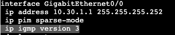
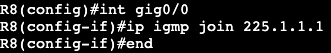
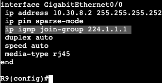
To add a group member I will go over to R8, go under the active interface towards the RP, and add an IGMP join message to our newly created Multicast Group.

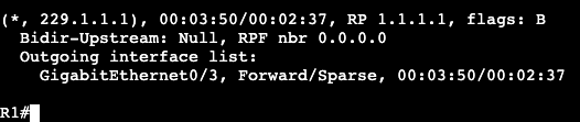
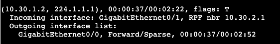
Now the mroute on R10 will show the succeeded RPF check and it will know the path for IGMP group 225.1.1.1.

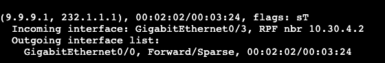
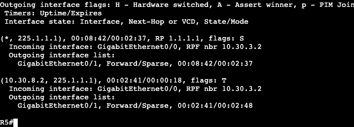
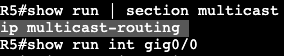
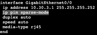
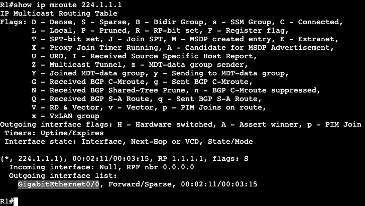
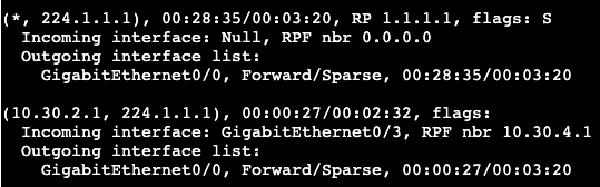
Again from R9 we’ll try pinging the multicast group 225.1.1.1. After we do this, now there’s a group member, there will be a successful ping response. In addition the ‘show ip mroute’ will show the full (S, G) for everything in the path. Here’s R5:

Auto-RP Security:

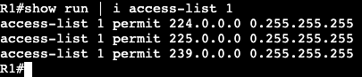
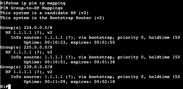
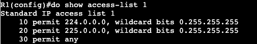
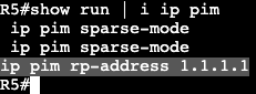
Currently on R1 we can see with the command ‘show ip pim rp mapping’ that we’re servicing the group 224.0.0.0/4. So basically everything. If we wanted to add an access-list to this we could do the follwowing:
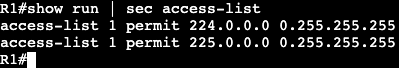
Create an ACL:

Add ACL to the pim RP mapping:

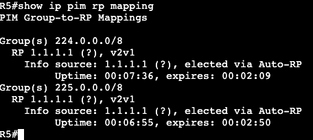
After running a ‘clear ip rp-mapping’ the ‘show ip rp mapping’ shows the serviced group has decreased to meet our ACL.

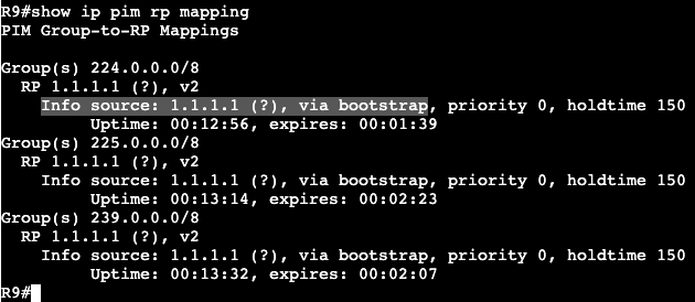
Same with another router outside of the RP

This essentially means if any router on the network tries to join a group that does not fall under 224.0.0.0/8, or 225.0.0.0/8, the network will fail to know what it should do.

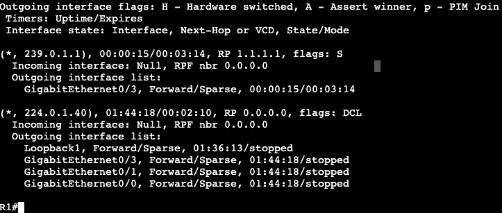
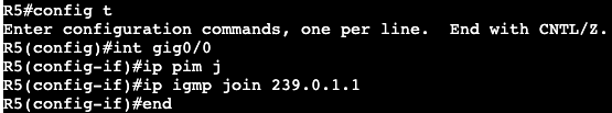
In the image above, after the ACL add, I’ll try to have R5 join group 239.0.1.1.

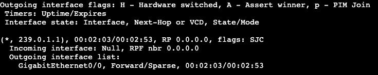
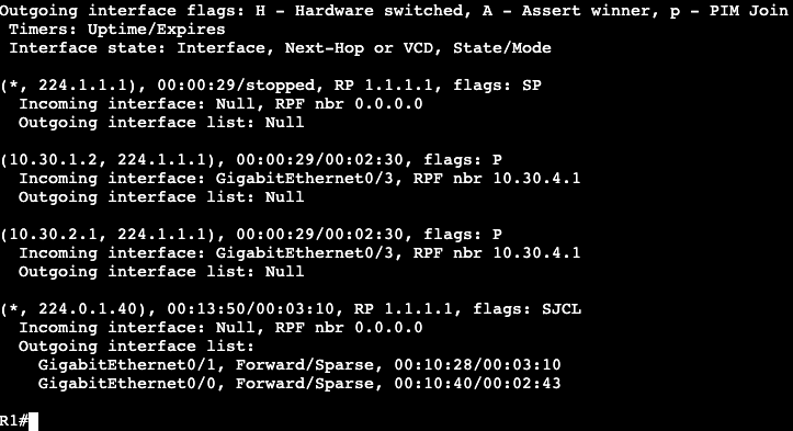
On R4 now, checking mroute for 239.0.1.1, it shows the incoming interface is Null. The reason for this is because the router does not know what Rendezvous Point is used for the new group.

After adding the permit any to access-list 1, then pinging the group 239.0.1.1, I can now see in R4 that it’s building the full SPT.

Multicast RPF Failures

  • Reverse Path Forwarding Check
    • PIM does not exchange its own topology.
    • PIM relies on IGP for loop free path selection.
    • RPF check is an extra data plane loop prevention technique.
  • RPF check performed on all incoming multicast packets.
    • If incoming multicast interface == outgoing unicast interface, RPF check passed.
    • If incoming multicast interface DOES NOT == outgoing unicast interface, RPF check fails, packet dropped.
  • RPF check changes depending on type of tree.
    • Shortest Path Trees (SPT)
      • Performs check against source
      • Used in (S,G) trees.
        • Pim Dense Mode
        • Pim Sparse Mode from RP to Source
        • Pim Sparse mode from Receiver to Source after SPT Switchover (S-bit set)
        • Pim Source Specific Multicast (SSM)
    • Shared Trees (RPT)
      • Perform RPF check against RP.
      • Used in (*,G) trees
        • Pim Sparse Mode from Receiver to RP before SPT switchover.
  • RPF check also performed on RP against Register messages.
    • RP must have route back to source that is being registered.
    • If no route, (S, G) state cannot be created.
  • Verify/Troubleshooting commands:
    • show ip mroute
    • show ip mroute count
    • show ip rpf
    • mtrace
    • debug ip pim
    • debug ip mfib pak
  • RPF controls how trees must be built, not how it can be built.
    • PIM join is sent out RPF interface for both (*,G) and (S,G)
    • Changing RPF results in traffic engineering for multicast.
    • You can override Unicast route table if there are static mroutes entered.
      • ip mroute x.x.x.x x.x.x.x x.x.x.x

PIM Sparse-Mode Config

The image above shows 10 routers all running in OSPF area 0. They are each advertising their own loopback interface into the OSPF domain – ie. R<#> = #.#.#.#/24. They will each get Multicast and PIM Sparse mode enabled on their transit interfaces.

In addition, each router will point to R1 as it’s Rendezvous Point at 1.1.1.1.

On R10 when trying to ping the multicast group 224.1.1.1, I will not get a response, but now on R1 there should be some information gathered.

‘show ip mroute’ on R1 will display a few things.

(10.30.1.2, 224.1.1.1)
– Shows the sender (R10) and the group the sender was trying to reach (224.1.1.1).
– Shows incoming interface on Gig0/3, RPF neighbor 10.30.4.1 (neighboring router interface).
– Outgoing interface in regular Unicast table is Incoming interface in Multicast table.

(*, 224.1.1.1)
– Going to be used by the receivers. Right now it shows outgoing interface as NULL because there are no receivers.

On the reverse side, lets now have a receiver ‘join’ the multicast group of 224.1.1.1. This will be completed in R9, where an IGMP join will be setup.

On R9 there’s only one link towards the RP, which is gig 0/0.

Now on the RP when looking at the group 224.1.1.1, there is an interface in the outgoing interface list. Gig0/0 is the interface pointing to R6, which is the closest to the new IGMP group member.

Now if we move up to R5 and take a look at the mroute table, we’ll see the following:

Shared tree that is pointed towards the Rendezvous Point (RP).

  • (S, G) – (Source, Group) – (*, 224.1.1.1)

And the source tree (Shortest path tree) which is rooted at the group sender.

  • (S, G) – (Source, Group) – (10.30.2.1, 224.1.1.1)
  • Notice the incoming interface is traffic coming from the source, and outgoing interface is where traffic goes to reach the RP.
  • The same can be seen on R4, which is another hop up the chain closer to the Rendezvous Point.

Mroute on R1 is going to show the shared tree and the (S,G).

SPT SWITCHOVER:

  • The RP is ultimately about creating the control plane for traffic from sender to receiver(s). If the RP is not actually in the data path between (S, G), then there’s no point in sending traffic to RP just to have it redirect to somewhere else. To accomplish taking the RP out of the next hop, SPT Switchover is completed.

Multicast Sparse Mode

  • RFC 4601
  • Uses ‘Pull’ model or explicit join.
  • Uses two tree types:
    • RPT – Shared tree
    • SPT – Shortest Path tree
    • NOTE
      • Dense mode uses only SPT
  • More scalable and usually better design choice then Dense mode.
    • Dense mode basically legacy.
  • Multicast tree determines how traffic is routed from sender to receiverS.
  • Source based tree
    • Uses shortest path from sender to receiver.
    • Dense mode or sparse mode
  • Shared trees
    • Uses shortest path from sender Rendezvous Point, then shortest path from RP to receiver.
    • Sparse mode only
    • Used for the following:
      • Eliminate flooding
      • Eliminate pruning
      • Making routing table more scalable.
  • Sparse Mode Operations:
    • Discover PIM neighbors and elect Designated Router.
    • Discover RP
    • Tell RP about sources.
    • Tell RP about receivers.
    • Build Shared Tree from Sender to Receivers through RP.
    • Join shortest path tree.
    • Leave shared tree.
    • Multicast Table Maintenance.
  • Rendezvous Point:
    • Used as reference point for root of shared tree.
    • Learns about sources from Unicast PIM Register messages.
      • Register message gives PIM an (S,G)
    • Learns about receivers through PIM Join messages.
      • Join message tells RP to add interface to OIL for (*,G)
    • Used to merge the two trees together.
    • Without RP, there will be zero registers and joins in PIM sparse mode.
    • As Root of all shared trees, RP must know all sources.
    • More operations:
      • When first hop router connected to sender hears traffic, a unicast Register is sent to RP.
        • Only DR sends register if multiple multicast routers available.
      • If RP accepts, it acknowledges with Register Stop and inserts (S,G) into Multicast table.
        • At this point only DR and RP know (S,G) mapping.
      • PIM Join
        • When last hop router receives IGMP Report, a PIM Join is generated up reverse path (tree) to RP.
        • All routers in reverse path install (*,G) and forward the Join hop-by-hop to the RP.
        • At this point all downstream routers toward receiver know (*,G).
      • Merging Trees
        • Once RP knows (S,G) from sender and (*,G) from receivers, RP sends PIM Join up reverse path to source.
        • All routers in between RP and source install (*,G) with outbound interface list pointing towards RP.
        • Once (S,G) begins, tree is built end to end through RP.
      • SPT
        • Shared tree is made of two Shortest Path Trees.
          • SPT from RP to sender
          • SPT from receiver to RP
          • SPT from receiver to sender (both combined) may not be same as shared tree.
            • result is shared tree not optimal.
            • Fix
              • Last hop router joins SPT to source with (S,G) Join.
              • Leaves RPT by sending (*,G) Prune to RP
            • Can be modified with ‘ip pim spt-threshold’.
  • Routing Table Maintenance:
    • PIM Dense and PIM Sparse use State Refresh to ensure feeds to not timeout.
      • (*,G) join sent to RP or up SPT to refresh the OIL.
    • Sparse Prune message can be used to speed up state information timeout if IGMP Leave is heard from end point.

Multicast General Info

How it works:

  • Source app sends UDP multicast traffic to group destination address.
  • Interested receivers join group address by signaling to routers on local area network.
  • Routers communicate to build loop free path (tree) from sender to receivers.
  • Portion of network without receivers will not receive that traffic for the group.
    • Saving resources – Advantage of multicast.

Use cases:

  • IPTV
  • Videoconferencing
  • VoIP On hold music.
  • Large scale data center replication.
  • Real time applications like stock tickers.

Group Addressing:
– Layer 3 and Layer 2 addressing

Control Plane:
– IGMP
– PIM
– MSDP
– MBGP

Data Plane
– Reverse Path Forwarding (RPF)
– Multicast Routing Table (MRIB/MFIB)

Multicast Group:

  • Address agreed upon by sender and receiver.
    • Source sends to destination address (group address)
    • Receivers are listening for traffic heading to that group.
  • Traffic always sent to a group, not group to sender.
  • Groups use layer 2 and layer 3 addressing.

IPv4 Addressing:

  • 224.0.0.0/4
  • Link Local
    • 224.0.0.0/24
  • Source Specific Multicast
    • 232.0.0.0/8
  • Administratively Scoped
    • 239.0.0.0/8

Layer 2 Addressing:

  • IPv4 address maps to MAC address which is forwarded for LAN.
  • Allows L2 switches forwarding in intelligent way.

Control Plane:

  • Who is sending traffic and to where?
  • Who is receiving traffic and for what groups?
  • How traffic should be forwarded
    • Tree
  • Built with combo of IGMP and PIM/MSDP

IGMP:

  • Used for host to signal to routers over L2/LAN.
    • Tells router that host is part of specific group.
  • Version 1
    • Message Type:
      • Host membership query
      • Host membership report
    • Report used to join group
    • Query used by router to see if members of the group still exist.
    • Replaced by version 2
  • Version 2
    • Adds
      • Querier election
        • If multiple routers on LAN segment that are running Multicast
      • Timers
        • Adds timers that speed up timeouts.
      • Group specific queries
        • Query sent to group address instead of all multicast hosts on segment.
      • Explicit Leave
        • Speeds up convergence when no hosts are part of group any longer.
    • Backwards compatible.
  • Version 3
    • Supports Source Specific Multicast
      • v1 and v2
        • (*,G)
      • v3
        • (S,G)
      • Receiver already knows the source sending multicast traffic.

Multicast Routing:

  • PIM
    • Router to router communication.
    • Builds loop free tree.
    • Versions 1 and 2
    • Sparse mode and Dense mode
  • Dense Mode
    • Implicit join
    • All traffic unless you say you don’t want it.
    • Uses Flood and Prune behavior.
  • Sparse Mode
    • Considered explicit join.
    • No traffic unless ask for it.
    • Uses Rendezvous Point to process join requests.

Multicast Data Plane:

  • Traffic begins to flow once tree is built.
  • Data Plane check prior to traffic flow
    • Reverse Path Forwarding (RPF)
      • Was traffic received on correct interface?
    • Multicast Routing Table (MRIB/MFIB)
      • What interface shuld I forward the packets out?

RPF Check:

  • PIM does not exchange topology info with routers.
    • Multicast traffic comes in, router looks at source IP address and incoming interface.
    • Normal Unicast CEF is checked for reverse path back to source.
    • Logic:
      • If incoming multicast interface == outgoing unicast interface, check has passed.
      • If incoming multicast interface DOES NOT == outgoing unicast interface, then packet is dropped because RPF failed.
    • Basically PIM uses the normal unicast topology/FIB/routing information to figure out there’s a loop free path/multicast tree.
      • Opposite of each other.