iBGP will not modify next hop as it advertises to its neighbor.
Can be modified with ‘neighbor <address> next-hop-self’
Update source IP is used as next hop.
Next hop can be modified using route map as well.
updates being received.
Configuration:
neighbor <address> route-map <name> in | out
Uses set clause
Next hop self on edge router
Peer can use same next hop on outbound updates to iBGP peers.
Same dynamic update group
Don’t need to include external links to IGP.
cons
Hinders fast convergence of external uplink failure.
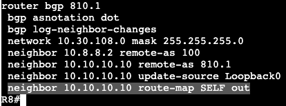
Changing ‘next hop self’ with route-map:
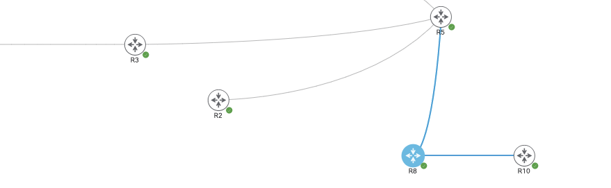
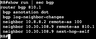
R8 and R10 are in AS810.1, iBGP peers, and R5 is an EBGP peer. R10 receives BGP routes from R5 via R8, but all next hops stay as is, the inbound IP address of 10.8.8.2 from R5. If R5 does not know how to reach that transit link, it will never add routes into its local RIB from R5. This can be changed with ‘next hop self’ in many ways, this is through a route map.
R8 will advertise next hop self via BGP through the route map method. Again, no functional difference between using the normal ‘next-hop-self’ under the global BGP config and this. Also- the next hop will look like whatever the ‘update source’ is setup as.
Difficult for migration to because the BGP process has to be deleted/restarted.
Configuration:
‘router bgp <sub-as>’
‘bgp confederation-id <main-as>‘
‘bgp confederation-peers <sub-as1 sub-as>
Only Sub-AS that the router is peering with.
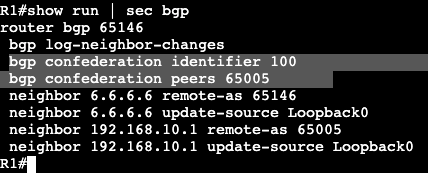
Example configuration:
In the example above the scope of the confederations configuration is all within AS 100, and the sub-AS peer is 65005.
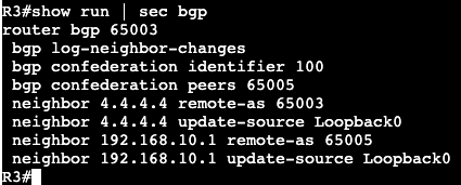
R1 is running EBGP (within the confederation) to R5 and iBGP to R6. The confederation configuration is very similar to regular BGP, it just has the two main commands, identifier and peers. The configuration on R3 and R2 are exactly the same except they have different Sub-AS numbers. R3 is below:
192.168.10.1 is L0 of R5
After this configuration on R1, R2, R3, and R5 there’s still no BGP adjacency between the different sub-AS’ – ie. R5 to R1 R3 and R2. The reason for this is because they’re all now technically running EBGP between each other. EBGP has the default rule that peers need to be directly connected, whereas iBGP has the default TTL 255. One of the fixes is to run the neighbor ‘disable-connected-check’.
After the above command is entered in both R1 and R5, adjacency comes up.
Another option to fix this is do EBGP Multi-hop. On R3 we’ll run the below command, as well as R5 for the other side.
The Multi-Hop command defaults to 255, above has added 2.
After entering the command ‘neighbor 192.168.10.1 ebgp-multihop 2’ on both sides, adjacency comes up very quickly. The same thing will be done on R2 to R5.
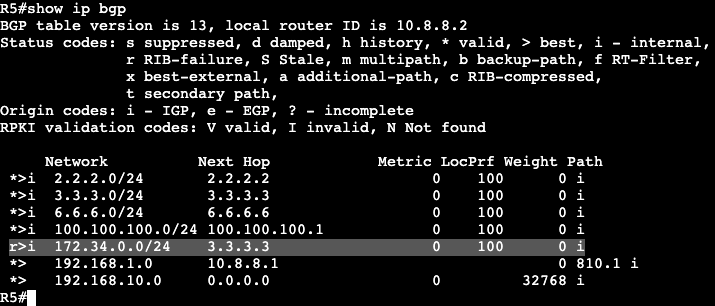
Now on R5 after neighbor adjacencies are up, ‘show ip bgp’ will show the sub-AS numbers in the path to reach different destinations.
If we look at the ‘normal’ EBGP peering to R8 however, the path to these destinations all appear to be coming from AS 100.
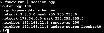
R3 is connected to R4 with the subnet 172.34.0.0/24 and it’s being advertised into BGP, and R5 is receiving that route (ignore RIB failure, ospf is running in background which is preferred over iBGP).
All of the other iBGP peers will not receive this route because of the default rules and loop preventions mechanisms. To allow R5 to pass on these routes to additional iBGP peers, we’ll need to make it function as a Route-Reflector.
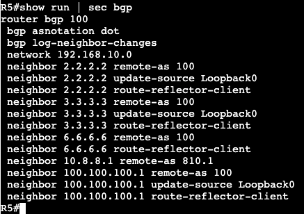
After adding the following command, ‘neighbor <neighbor ip> route-reflector-client’, the routers neighboring with R5 are now receiving the advertised route from R3.
Route advertisements will differ depending on whether the advertisement is occurring over iBGP or EBGP. Some of the important differences have to do with next hops and iBGP full mesh.
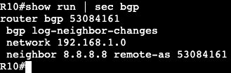
Below are three routers running BGP. R8 and R10 are running iBGP in ASN 810.1, while R8 and R5 are running EBGP, R5 being in ASN 100. R8 and R10 have OSPF for internal loopback connectivity. R5 is advertising it’s loopback network 192.168.10.0/24 down to R8, and R10 is advertising a loopback network of 192.168.1.0/24.
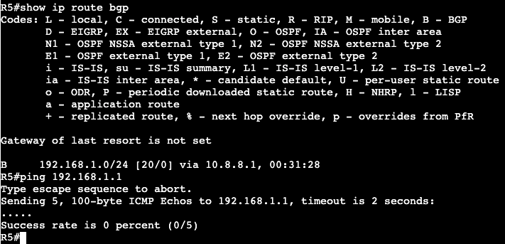
R5:
R10:
When R5 tries pinging R10’s advertised loopback, it will not succeed, even though R5 has a valid route via BGP in it’s routing table.
Looking on R10, a ‘show ip bgp’ displays zero ‘>’ next to R5’s route, which means that it was not actually added to the routing table.
Drilling into this even further, BGP shows that the next hop (10.8.8.2, R5) is not accessible in R10’s routing table.
What this displays is how iBGP will advertise to its neighbors. The EBGP peer will advertise 1 hop further into its autonomous system but will not change the next hop. This can be troublesome for iBGP neighbors who do not have route information for the transit to another AS.
A solution to resolve this issue is by doing BGP ‘Next Hop Self’. On R8 the config for this is under the router bgp AS.
The command is after specifying which neighbor this should be applied on. This alone will not change the advertisement. A route refresh needs to occur.
A ‘* out’ will refresh the bgp table without taking the adjacency down.
Now on R10 we’ll see the route added to the routing table and the next hop advertised as R8’s internal Loopback address that R10 is peering with.
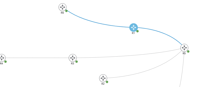
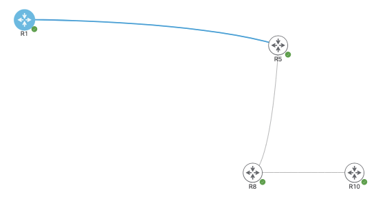
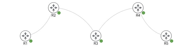
Below is an image with another BGP neighbor in the mix, R1. R1 is going to be in AS 100 and an iBGP peer with R5.
R1 and R5 have reachability via OSPF and they’re both peering over their Loopback0 IP addresses.
R1 L0 – 100.100.100.1/24 R5 L0 – 192.168.10.1/24
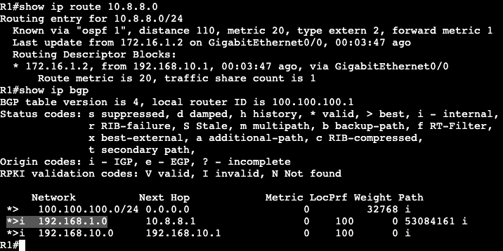
After the peers are up here’s what a ‘show ip bgp’ looks like on R1:
All looks good except for prefix 192.168.1.0, which is a subnet back on R10 in AS 810.1. The reason for this is the next hop again, 10.8.8.1, is not reachable from R1. A fix for this is to perform next hop self again when setting up peering from R5 to R1, or we can simply inject that route into the OSPF domain for underlying reachability, which is the other option – add the routing into the BGP IGP.
On R5 we can see that 10.8.8.0 is a directly connected network, and all we need to do is add that interface into OSPF, or redistribute connected.
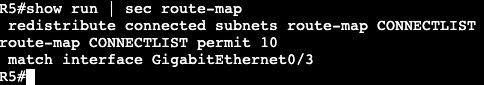
On R5 the 10.8.8.0 subnet is on GigabitEthernet0/3, and below is a route-map matching on that interface.
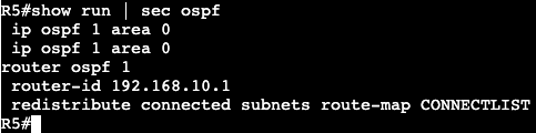
The route-map will then get added into the OSPF process with redistribution. This will allow only what’s in the route-map to get redistributed.
Now on R1 the 10.8.8.0 network is visible via OSPF, and the BGP table shows R10’s loopback subnet has made it to the RIB.
Main Takeway:
By default when eBGP advertises a route to a remote AS, the next hop for the remote AS will be the originating advertising router.
If this route gets advertised further into iBGP, the route next hop will not change, it will remain the IP of the remote AS router.
Fixes for this are advertising transit path into an IGP, or setting the inbound router as next-hop self – ie. next hop self to iBGP peer.
Link State protocol, knows entire topology of an area.
Most filtering occurs at area borders and autonomous system borders.
Filtering with prefix-list:
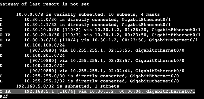
In the image above, R5 and R4 are in area 0, R2, R3 and R4 are in area 146. R5 is advertising the the loopback 192.168.5.1/32, which can be seen as an inter area route in R2.
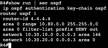
To filter out this route a prefix list will need to be created on the ABR between 146 and 0, which is R4.
Configuration:
Above shows the prefix list is denying specifically the /32 host route. The next sequence down will permit all other prefixes. This list will then get applied to R4’s router OSPF process configuration.
Once the filter-list command is added, R5 no longer will see the subnet that was denied in the prefix list. The ending of the command ‘out’ is in place because we’re filtering a route coming from area 0, out to area 146.
NOTE:
Distribute-list is used with a standard access-list to deny traffic WITHIN an area or to a routing table of a specific host.
Distribute-list does not stop LSDBs, just stops a route from entering RIB post topology table.
Filter-lists are used with prefix-lists to stop an LSA summary (Type 3) from entering an area.