All devices within same area must have same link state database.
Summarization cannot happen anywhere within an area.
Summarization can only occur between areas or at ASBR.
Internal summarization
Summarizes type 1 LSA into type 3 LSA.
ABRs
External summarization
Summarizes type 5 into type 5.
Summarizes type 7 into type 7.
Performed on ASBRs.
Local Discard/Null0
When summarizing, OSPF automatically creates local discard route.
If longest match IS the summary address, there’s something wrong.
There should always be a more specific route.
End result is that summary router cannot fallback to default.
Can be disabled with ‘no discard-route’.
Example/configuration:
In the image above we have five routers running OSPF and EIGRP. In OSPF perspective, Backbone area and area 146, with one external domain. This means there are two opportunities to summarize. Summarization can occur on the ABR or the ASBR. R5 has the following interfaces being advertised into OSPF.
These loopback IPs need to be summarized into OSPF Area 146, which can be accomplished with the following command:
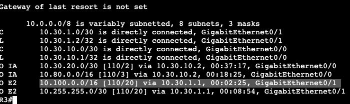
This is under the router ospf process configuration, and area number is specifying what area the prefixes came from that are being summarized. On R3 we can now see that the 10.80.0.0/16 is what’s being installed in the RIB.
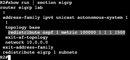
Next step is doing a summarization on the ASBR via redistribution. On R1 there are the following interfaces being advertised into EIGRP AS 1.
Which can be seen in R2’s routing table.
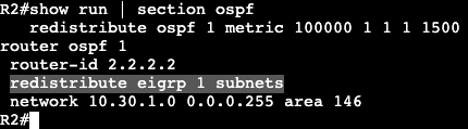
Redistribution is the first step.
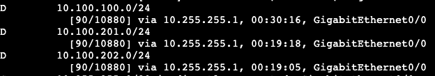
Now in R3’s routing table we’ll find E2 routes for the redistributed EIGRP routes outside of OSPF.
10.255.255.0/30 is a transit network that can be ignored, but the routes starting in 10.100.x.x will now be summarized with the below command.
And now on R3 we’re receiving the summary /16 route for external/redistributed prefixes.
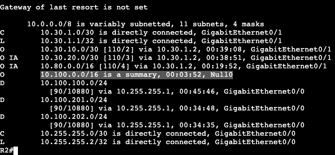
Something else to note- on the ASBR R2, the routing table has a null route for the 10.100.0.0/16.
10Gbps links and higher need the auto reference bandwidth changed.
Ultimately cost is based off Reference Bandwidth / Interface bandwidth
Path Preference
Intra (O)
Inter Area (O IA)
E1
N1
E2
N2
Link cost does not matter in the order above.
Link cost only matters when multiple routes to same destination have same metric type.
Cost Modification:
‘interface bandwidth’
‘Interface ip ospf cost’
‘process auto-cost’
‘process neighbor cost’
Virtual Link Cost:
Inherit cost from SPF cost between Virtual Link Endpoints.
Must have cost below 65535 to initialize.
Higher than 65535 could occur if ref bandwidth is high and Virtual Link transits legacy links.
ex. Ref bandwidth is 40Gbps and VL transits a T1.
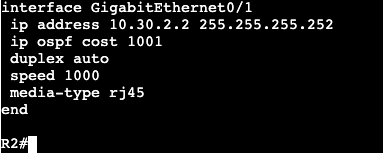
Interface OSPF Cost Value:
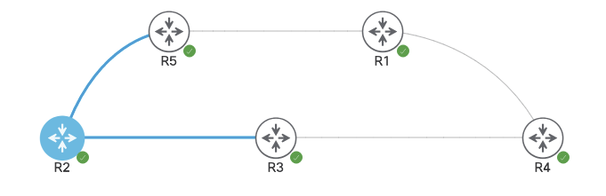
In the below image all routers are running area 0. R4 is advertising loopback IPs 1.1.1.1 and 2.2.2.2 into the area, and R2’s path to both advertised subnets is through R3 due to values over that link.
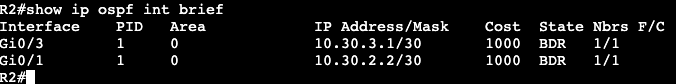
Looking at the OSPF costs of R2’s interfaces shows each with a cost of 1000 due to reference bandwidth set at 1000000.
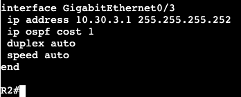
If the cost command is applied to Gi0/3 as value 1 and Gi0/1 as 1001, we’ll see load balancing occur.
The reason for this is both paths will add up to the same metric to routes 1.1.1.1 and 2.2.2.2, value 2002.
Another way of changing this is through the Bandwidth command under the interface. This will most likely require the reference bandwidth changed, however.
OSPF Scalability is done by minimizing the following:
Reachability Information
Flooding Domains
Areas
Do not hide reachability information, but hide graph from other areas.
SPF only runs inside area (intra area)
Reachability summarization
Reduces number of prefixes.
Per-LSA Summarization
Removes all IA routes, replaces with teh shortest match possible, a default route.
This is how Stub Areas work.
Filtering
Enforced at ABR
ABRs control which LSAs enter neighboring areas.
Types3, 4, and 5 are filtered depending on the Stub area type.
All routers in the area must agree on specific stub flag.
STUB AREA TYPES:
Stub Area:
Stops external routes
LSA Type 5
Totally Stubby Area:
Stops inter-area and external routes
Not-So-Stubby Area:
Stops external but allows local redistribution.
Not-So-Totally-Stubby Area:
Stops inter-area and external but allows local redistribution.
Stub Logic:
Stub router/area knows how to reach ABR.
ABR knows how to reach ASBRs.
ASBRs know where external routes are.
ALL THAT IS NEEDED IS DEFAULT TO ABR.
Technical results:
ABR removes LSAs 4 and 5.
ABR originates default route into stub area.
Stub Configuration:
Above there’s three routers: R2 – Area 0, advertising Loopbacks to R3 R3 – Area 0 to R2, Area 1 to R4
R4 is receiving the following routes via OSPF, including the E2 externals being redistributed from outside the AS to R2.
To change area 1 to a Stub area, the below commands will be run on R3 and R4:
‘area 1 stub’ under router ospf process
‘area 1 stub’ under router ospf process
After the commands are entered, the adjacency between R3 and R4 goes down, then back up. The routing table on R4 now shows below:
There is a default route and no longer any external E2 routes from the redistribution. This is because Stub will remove only the LSA 4 & LSA5. LSA 3 (IA) is still showing up in the routing table.
Totally Stubby Logic:
Know how to reach ABR.
ABR knows how to reach other areas and ASBRs.
ASBRs know how to reach Externals.
If default to ABR, no need to External routes or inter-area.
Totally Stubby results:
Removes LSAs 3, 4 and 5.
Adds default from ABR into area.
Totally Stubby Configuration:
Continuing on with the three router example (4 if counting routes that are coming from redistribution on R2, the area 1 ABR needs an addition to its stub command. no-summary
Now on R4’s routing table, all that should be available via OSPF is a default route from the ABR (R3).
Not-So-Stubby Area Logic:
Filters like Stub area but allows local redistribution.
Local redistribution is LSA type 7, which gets turned into LSA type 5 by ABR for advertising into rest of OSPF domain.
No default route provided from ABR into NSSA.
NSSA Configuration:
R4 is still configured as a Totally Stub, so it’s only receiving a default route from the OSPF domain. In addition there is now R1 that is an EIGRP neighbor advertising the route 96.76.43.136.0/29 to R4.
When trying to allow redistribution from EIGRP into the Totally Stub OSPF domain, an error occurs saying it cannot be done. In order to do this the command ‘area 1 nssa’ needs to be added on both R3 and R4.
The routing table now on R4 receives no default route from the OSPF ABR and no external routes from any other area except for its own.
the routing table now on R3 (ABR) receives N2 routes showing that locally redistributed route from R4.
Not-So-Totally-Stubby-Area Logic:
Blocks inter-area and External, allows local redistribution.
Combines NSSA with Totally Stubby.
Result:
Redistributing router generates LSA 7
ABR Changes to LSA 5 when advertising into rest of OSPF domain.
ABR Removes LSA 3, 4, and 5.
ABR Originates default route.
Not-So-Totally-Stubby-Area configuration:
Same topology above, the configuration needs to be changed now on R3. Currently R3 and R4 running area 1 are setup as a NSSA, so command ‘area 1 nssa’ is added under each router ospf process. Below is the only configuration change that’s needed.
Now the routing table for R4 shows following:
It has a default route but still receives the redistributed LSA 7.
A discontiguous area is when there’s an area that’s not directly connected to area 0.
Does not work.
Virtual Link Requirements
Must be used over a normal area.
no stub.
No filtering applied over transit area.
Inherits cost through SPF.
Must be lower than 65535
Runs as demand circuit.
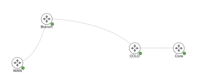
In the image below there are four routers. Core and COLO are both running area 0, but COLO to Branch is running Area 1. From Branch to WAN router is running area 0 again, which obviously doesn’t work.
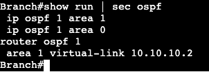
When advertising Loopback interfaces from Core into the OSPF domain, Branch and WAN are failing to receive any updates, but COLO receives them just fine. A virtual link can be created to fix this poor topology. The virtual link will start under the COLO router.
The virtual link on the COLO router will receive the proper command with the neighboring router-id of Branch, where we’re terminating the virtual link.
Same config on the Branch side, but with the OSPF router-id of COLO.
Immediately after its entered there’s a console message showing there’s an adjacency, but on VL0.
And now reachability is allowed from both WAN and Branch routers.
OSPF works differently depending on the media of interface the protocol is enabled on.
Defines network types to deal with specific types of media.
Next hop, timers, adjacency formation are different per media.
All Network types:
Broadcast
Non-Broadcast
Point to Point
Point to Multipoint
Point to Multipoint Non Broadcast
Loopback
Network types do not need to match.
Properties such as timers need to match however.
LSA Type 2:
Type 2 is what makes differing network types compatible.
Generated by DR.
Enhances performance of OSPF on a shared segment between nodes.
Reduces adjacencies.
Reduces LSA flooding replication.
Simplifies SPF.
Network types that use LSA Type 2
Broadcast
Non-Broadcast
Network types that do not:
Point to Point
Point to Multipoint
Point to Multipoint non-Broadcast
Default media types are Multiaccess.
ie. Ethernet, Token Ring, FDDI
Sends hellos and updates on Multicast.
224.0.0.5 – All SPF Routers
224.0.0.6 – DR
OSPF Network non-Broadcast
Examples Frame Relay and ATM
Sends hellos as unicast
Manually defined neighbors with ‘neighbor’ command.
Still uses DR/BDR
DR and BDR Process:
DR
Forms adjacency with all routers on the multiaccess network.
listens for updates on multicast .6
Re-floods updates back on the segment at multicast .5
Does not modify next hop value.
BDR
Used for a DR backup.
Does not flood updates.
DROTHER
Any OSPF speaker not DR or BDR on a multiaccess network.
Form full adjacency with DR and BDR
Stop at Extart/2-way with each other.
DR/BDR are chosen through election
Based on interface priority and Router-ID
Priority
0-255
Higher = Better
0 = Never
Router-ID
Highest loopback/interface IP.
Can be statically set.
Higher = Better
Uses Wait timer to stop pre-emption of current DR/BDR
OSPF Network Point-to-Point
Default on the following:
HDLC, PPP, GRE Tunnel
Hellos at 224.0.0.5
no DR/BDR
Supports only two neighbors on the link.
OSPF Network Point-to-Multipoint
Treats network as collection of point to point networks.
Hellos sent to 224.0.0.5
No DR/BDR
Special Next-Hop processing.
OSPF Network Point to Multipoint non-Broadcast
Same as point to multipoint but sends hellos as unicast.
Manually defined neighbors – ‘neighbor’ command under OSPF.
Allows for per-VC OSPF cost over NBMA.
No DR/BDR
Special Next-Hop processing
OSPF Network type Loopback
Advertises link as /32 stub host route.
‘ip ospf network point-to-point’ used to disable this behavior.
Election Modification:
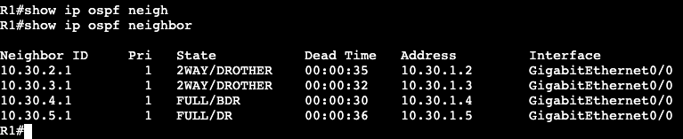
The five routers below are all running OSPF over the shared multiaccess/ethernet network. From R1’s CLI it shows the devices have formed adjacency like they should in a Broadcast network type.
The DR is R5/10.30.5.1, and the is R4/10.30.4.1. This is because the default winner of the election is going to be the highest router-id.
A quick way of changing the DR is going on the active DR and setting OSPF priority to 0. This will remove the Router (R5 in this case) completely from the election process.
The priority change above made R5’s adjacency flap, and now from R1’s perspective R3 is the BDR, R4 is the DR.
Note:
If running a DMVPN Hub and Spoke while using Broadcast/DR/BDR OSPF network, make sure all spokes have priority 0 setup on interfaces so they do not become the DR. If one of the spokes becomes the DR, none of the other spokes will receive routing updates.
All OSPF nodes within area agree on that area’s topology.
Full SPF occurs within an area when there is a change.
Inter-Area routing
Hides topology details from one area to the next.
Saves router resources by having multiple areas.
Backbone Area:
Area 0
All inter-area traffic must pass through the backbone.
Loop prevention mechanism.
All non-area 0 areas need to have direct connection to area 0.
ABR:
Area Border Router
Link in area 0 and non-backbone area.
Where summarization occurs.
ASBR:
At least one link in OSPF domain.
At least one link not in OSPF domain
ie. another routing protocol AS.
Performs redistribution between domains.
LSA Types:
Intra-Area Routes
Labeled ‘O’ in routing table
LSA types 1 & 2
Inter-Area Routes
Labeled ‘O IA’ in routing table
LSA types 3 & 4
External Routes
labeled ‘E1/E2’ in routing table
LSA type 5
labeled ‘N1/N2’ in routing table
LSA type 7
LSA1:
Generated by every router.
Does not flood out local area.
Describes link costs, neighbors.
Builds graph inside area.
LSA2:
Generated by DR on multiaccess.
Local area significant.
Describes who is adjacent to DR and their costs.
Reduces flooding.
LSA3:
Used for inter-area routing.
These LSAs can be seen in the OSPF database via ‘Summary Net Link States’ on R5, coming from the ABR, R3.
10.40.1.0 & 10.42.1.1 are both coming from R1 in area 10
The ABR (R3) will hide the actual path to these destinations, but continue providing the cost. SPF does not run when advertising routes between areas. Inter-area routes is similar to how distance vector operates.
LSA4
Generated by ABR
Flooded between backbone and non-backbone areas.
Describes ABR’s reachability to ASBRs in other areas.
Inter-area external routing is similar to distance vector as well.
SPF is not run, routing by rumor.
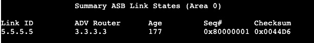
LSA4 can be seen via redistribution. In the database its hows up as ‘Summary ASB Link States’
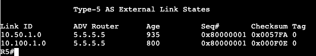
The advertising router is R3 with the router-id 3.3.3.3. Added into the topology is another router called ‘EIGRP_EX’. This new router is advertising the two prefixes 10.100.1.0 and 10.50.1.0 with EIGRP over to the ASBR, ‘R1’. R1 is then redistributing these into the OSPF domain.
The LSA4 is for area border routers, and LSA5 will be for autonomous system border routers.
LSA5
Flooded to all non-stub areas.
Comes from ASBR – redistribution
Metric types show up as E1 or E2.
E2 is default, will keep same metric.
E1 will change metric per hop like normal OSPF.
E1/Type 1 is preferred over E2.
Type 5s will show up in the database called ‘Type-5 AS External Link States’.
Point to Multipoint will change the OSPF timers on the interface to something that’s different than the default for Broadcast/Multiaccess and Point-to-point.
If using point-to-multipoint with Broadcast/Multiaccess or point-to-point, the hello timers will need to be changed on one of the sides to match.
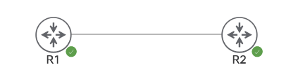
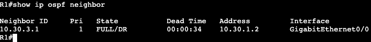
The image below shows two routers running OSPF. R5 is operating in point-to-multipoint, and R3 is running in normal broadcast.
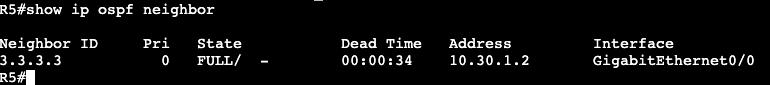
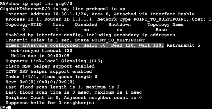
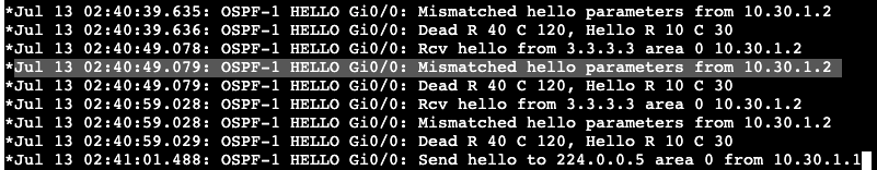
Running a ‘show ip ospf int gig0/0’ shows that R5’s interface is running in point-to-multipoint and it’s timers are 30, 120, 120.
The router R5 is trying to form an adjacency with is running in normal broadcast mode, which sets the Hello timer to 10, 40, 40.
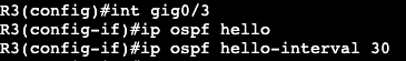
Adding a ‘debug ip ospf hello’ and bouncing R5’s interface shows the problem as well. What needs to be configured are the hello timers on R5 or R3 to match. On R3 the below command was added and the adjacency came up between broadcast and point-to-multipoint networks.
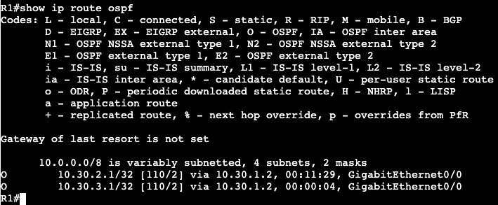
Above we can see the intervals were changed on R3’s interface, and below the adjacency shows with a much higher dead time than the default 10 seconds in a broadcast or point-to-point network.
This example in general is a bit odd because it’s forming an adjacency between a Broadcast network and a point-to-multipoint. It doesn’t appear as if it should actually be working. When I changed the hello interval to match on both sides, the adjacency came up. When I tried exchanging routes I could not get it to work. Then I took the adjacency down and could not get it to form again until I set the broadcast to point-to-point. Routes began exchanging between both nodes as well. In general the timers change is still valid though. The hello interval would have had to be changed if I was working with a point-to-point network type the entire time.
Correction – The Point-to-Multipoint and Broadcast network types are not compatible. Compatibility depends on whether the LSA Type 2 (DR/BDR) is being used. Type 2 is used in broadcast and not in Point-to-Multipoint.