IPv6 General Discovery/Addressing

  • RFC 2460 – IPv6
  • Larger address space
    • IPv4 – 32 bit address space
    • IPv6 – 128 bit address space
  • Address Types:
    • Link Local
      • FE80::/10
      • IPv4 equivalent – 169.254.x.x
      • Never routable.
      • Uses:
        • Stateless Address Auto-configuration (SLAAC)
        • Neighbor Discovery
        • Router Discovery
    • Site Local
      • FEC0::/10
      • No one could agree on what a site is.
        • Deprecated in RFC 3879
    • Unique Local
      • Equivalent to RFC 1918
      • ‘Private’
      • Likely unique but not routable over global BGP table.
    • Global Unicast
      • Technically everything else.
        • 2000::/3
      • Per RFC
        • End host must have 64-bit interface ID
        • Use EUI-64 format for interface ID.
    • Modified EUI-64
      • RFC 4291
      • Ethernet MAC to EUI-64 conversion
        • Invert Universal/Local bit
          • 7th most significant
        • Insert padding – 0xFF 0xFE in the middle of address.
    • IPv6 Temporary Addresses
      • RFC 4941
      • MSDN – IPv6 identifiers
        • Randomly generated interface identifiers.
      • Prevents tracking users based on MAC address.
        • EUI-64 result is always the same for a given MAC address.
    • IPv6 Address Resolution
      • RFC 4861
      • ICMPv6 neighbor discovery for layer 3 to layer 2 resolution.
        • Replacement for ARP.
      • Neighbor Solicitation
        • Equivalent to ARP Request.
      • Neighbor Advertisement
        • Equivalent of ARP reply.
      • Router Solicitation
        • Trying to find Gateway.
      • Router Advertisement
        • Use me for routing.

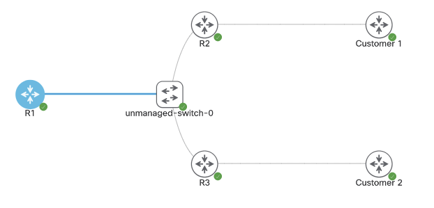
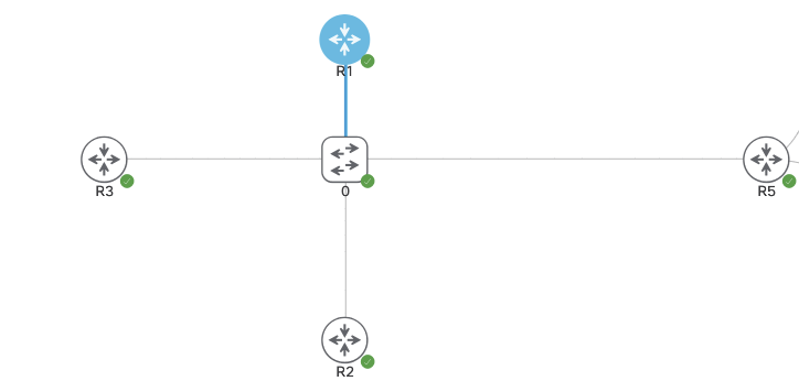
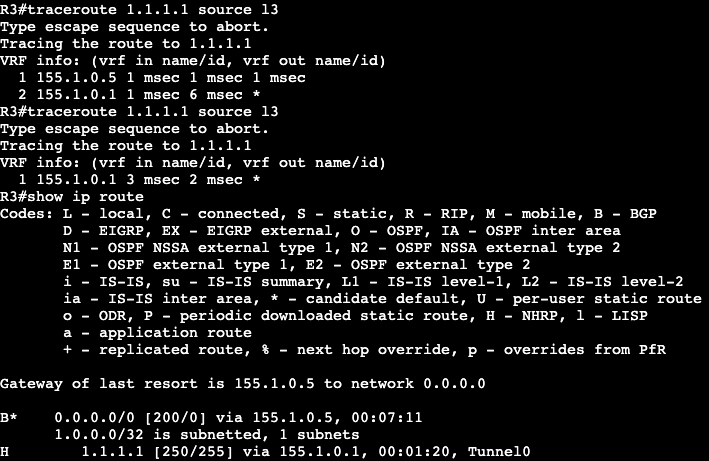
In this image we have R3 and R1 connected via both Gig0/3 interfaces. Interface configs below:

R3
R1

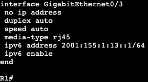
The commands ‘ipv6 enable’ and ‘ipv6 address <address>’ need to be added for unicast routing to work. In addition, the global config command ‘ipv6 unicast-routing’ needs to be entered for IPv6 to function on the box at all.

Once we successfully ping across from R1 to R3, the IPv6 neighbor table will be created. Similar to a ‘show ip arp’ in IPv4.

The table will respond with R3’s link local and global unicast address. Note- this mapping requires ICMPv6 to be enabled. If ICMPv6 is disabled, most IPv6 functionality will break with it.

SLAAC:

  • Automatically assigns IPv6 address for every on-link prefix.
    • Only works with /64s.
    • Duplicate Address Detection (DAD) used to verify uniqueness of generated address.
  • NOT DHCPv6.
    • Does not include router options like DNS.

On router R1 we can add a SLAAC address to the interface gig0/3 with the command ‘ipv6 autoconfig’. That will automatically generate an address which can be seen with a ‘show ipv6 interface gig0/3’.

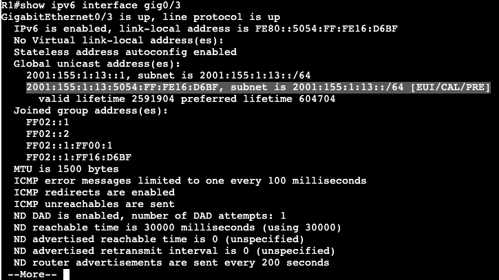
Within the address the FF:FE is found.

  • SLAAC often works alongside DHCPv6.
    • Options are set in RA messages
    • Tells host there is DHCPv6 server available for addressing options.
  • Other-Config-Flag
    • Use DHCPv6 to receive just addressing options (DNS,TFTP,etc.)
    • ‘ipv6 nd other-config-flag’
  • Managed-Config-Flag
    • Use DHCPv6 for both addressing and options.
    • ‘ipv6 nd managed-config-flag’

Host Default Routing

  • Hosts do not receive gateway from DHCPv6
  • First hop v6 router discovered through Neighbor Discovery and Router Advertisement messages.

IPv6 General Prefix

  • Can be defined to act as shortcut.
    • e.g. if organization is assigned a /32, then all prefixes should be derived from this /32.
    • helps in renumbering scenario.
  • Defined globally as:
    • ‘ipv6 general-prefix <NAME_OF_PREFIX> 2001:123::/32
  • Applied to link as
    • ‘ipv6 address <Name of Prefix> ::1/64
  • General prefix and subnet are merged to derive full address.

Global config command example:

Interface config command example:

The prefix that was added to the interface:

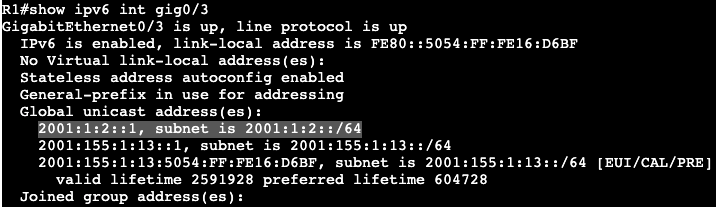
Ultimately a shortcut for assigning prefixes to interfaces.

MPLS and FlexVPN

Above is the topology being setup for MPLS over FlexVPN. The main goal is to have connectivity between Customer 1 and Customer 2.

First steps are configuring FlexVPN on the Hub, R1.

  • Keyring
  • Authorization policy
  • IKEV2 Profile
  • IPSEC Profile
  • Dynamic VTI
  • VRF
  • MP-BGP

Configuration for Spoke 1:

  • Keyring
  • IKEV2 Authorization Policy
  • IKEV2 PROFILE
  • IPSEC Profile
  • Dynamic VTI
  • VRF
NOTE- this VRF is being assigned to Gig0/3 towards the Customer as well.
  • MP-BGP

Configuration for Spoke 2:

  • VRF
NOTE- this VRF is being assigned to Gig0/3 towards the Customer as well.
  • IKEV2 Authorization Policy
  • KEYRING
  • IKEV2 Profile:
  • Dynamic VTI:
  • BGP:

FlexVPN Spoke to Spoke/DMVPN

  • FlexVPN can be setup with NHRP to run a DMVPN type setup.
  • Spokes will communicate directly with each other via NHRP resolution.
    • NHRP Registration does not exist with FlexVPN.

Topology used is below:

Right now it’s a normal hub and spoke topology with FlexVPN. All router loopbacks are being advertised over IKEV2. R1 has a virtual template setup.

To enable spoke to spoke communication, we’ll need to enable NHRP under the Virtual-Template interface. This cannot be completed however if there’s an active VPN tunnel running over the interface. Removing the SA requires shutting down the interface R1 is connected to. The SA does not completely leave the box for a few minutes after.

Under the Virtual-Template interface on our hub we’ll add the two NHRP commands with a network-id of 1. Then on the spokes a dynamic VTI is required for spoke to spoke communication. This will require a Virtual-Template as well using ip unnumbered Tunnel #.

In addition the NHRP commands need to be added to the existing static VTI.

When spoke to spoke communication is needed, both spoke routers will need to authenticate with each other. That will require using the existing keyring.

All of the above will need to be configured for additional spokes. The same has been applied to R3, but with peer IPs that work.

List

  • The following was configured:
    • NHRP Redirect and network-id under Hub Virtual-Template
    • A Virtual-Template Interface on each spoke with the following:
      • IP Unnumbered
      • NHRP ID and shortcut <‘virtual-template #’>
      • Tunnel source
      • IPSEC profile
    • New Peer under Keyring
    • NHRP Network ID and Shortcut under Tunnel 0

Now when looking at the route table of our hub, we’ll see the following static routes associated with Virtual-Access interfaces.

On the spokes we’ll see initially only static routes for the hub loopback. If we run a ping from spoke to spoke though, we’ll see that R2 will receive override routes once the NHRP redirect process has completed.

In addition our virtual access interface(s) will go up when the spoke to spoke tunnel is functioning.

FlexVPN – Hub/Spoke

The topology above is going to setup a DMVPN type scenario but it’s going to run FlexVPN. The shared subnet the three routers are connected to is 10.30.1.0/29.

R1: Loopback 1 – 172.16.1.254
R2: Loopback 2 – 2.2.2.2/32
R3: Loopback3 – 3.3.3.3/32

Hub:

  • Keyring
    • Using quad 0 for remote addresses (any)
    • Same PSK across the board.
  • AAA authorization settings (IKEv2 Routing)(‘aaa new-model’)
    • Using routing via IKEv2
    • Requires access list which is any.
  • IKEv2 Profile
    • Identity for simplicity is ‘any’
  • IPSEC Profile
    • IPSEC profile that specifies the IKEv2 profile
  • Virtual-Template
    • The virtual template is a virtual interface, but the IP address cannot be applied directly to it. It requires unnumbered with the loopback interface we’re connecting to each spoke with.

Spoke:

  • Keyring
  • Authorization Policy
  • IKEv2 Profile
  • IPSEC Profile
  • Static VTI
    • Note there is no virtual template on the spokes, just the hub.
  • Verify
    • ‘show crypto ikev2 sa’
    • ‘show crypto ipsec sa’

FlexVPN w/out Defaults

  • Without defaults, below configuration list is needed:
    • IKEv2
      • Proposal
      • Policy
      • Keyring
      • Profile
    • IPSEC
      • Transform set
      • Profile
  • IKEv2 Proposal
    • Used for normal IPSEC negotiation
      • DH group
      • Encryption – AES
      • Integrity – SHA
  • Tunnel Interface
    • Attaching VPN config
  • IKEv2 policy
    • Container for proposal that was just created
  • IKEv2 Keyring
    • Contains authentication and specifies the remote host.
      • PSK or RSA/Certificate
  • IKEv2 Profile
    • Contains identity and authentication we want to use.
      • DOES NOT CONTAIN ACTUAL PSK
      • SORT OF REPETITIVE BUT KEYRING GETS ADDED TO THIS PROFILE
  • IPSEC Transform-Set
    • Specifies encryption and hashing algorithms.
      • Under TS the tunnel mode can be set as well.
        • ie. Tunnel or Transport. Default is Tunnel.
  • IPSEC Profile
    • Glues together the IKEv2 profile and Transform set
  • Tunnel Interface
    • Specifies normal GRE operation and attaches IPSEC profile to the tunnel.
  • Disable Smart Defaults (optional)
    • If needed, can disable the smart defaults

‘no crypto ikev2 policy default’
‘no crypto ipsec profile default’
‘no crypto ipsec transform-set default’
‘no crypto ikev2 proposal default’

  • Verify Tunnel/Protection

Note the default IKEv2 policy is disabled.

Shows specifics of VPN IKEv2 settings.

Shows a security association exists for IKEv2.

Note default profile is disabled.

Shows there is a security association and we have packet encaps/decaps.

Flex VPN Site to Site w/defaults – Simplicities

  • Ultimately need minimal configuration to make the VPN tunnels go.
  • IKEv2 VPN typical requirements:
    • IKEv2 proposal
    • IKEv2 keyring
    • IKEv2 profile
    • IKEv2 policy
    • IPSEC ts
    • IPSEC profile

  • Smart Defaults allow operator to only configure:
    • Keyring
    • IKEv2 profile
    • Tunnel interface
  • Keyring example
  • IKEv2 Profile example
  • Tunnel interface

IPSEC configuration for tunnel interface only requires applying IPSEC profile.

FlexVPN General

  • Cisco’s IOS implementation of IKEv2
    • Unified configuration framework for L2L, remote access and spoke-spoke VPNs
      • Tunnel interfaces.
  • FlexVPN components
    • Proposal, policy, credential store, profile
    • Tunnel interface.
  • Other
    • IPSEC Profile
    • Routing
  • FlexVPN Proposal
    • Set of algorithms used to protect IKE_SA_INIT
      • More than one function can be configured for the same security feature.
        • ‘crypto ikev2 proposal <name>
          • ‘encryption <enc type>’
          • ‘integrity <inte type>
          • ‘group <dh group>’
          • ‘prf <prf type>’
        • AES in Galois/Counter mode (AES-GCM) combined algorithm.
          • Requires PRF to be manually configured.
        • DH Groups 19/20 are Elliptic Curve Algorithms (ECDH)
  • Enables a proposal
    • Policy can match based on FVRF or local IP.
      • ‘crypto ikev2 policy <name>’
        • ‘proposal <name>’
        • ‘match fvrf <name>’
        • ‘match address local <ipv4 or ipv6>
  • Credential Store
    • Stores authentication data
      • Trustpoint (‘crypto pki trustpoint’)
      • Keys (can now be asymmetric)
        • Keyring (‘crypto ikev2 keyring’)
        • In-profile (‘authentication <local|remote> pre-share’)
  • IKEv2/FlexVPN profile
    • Stores non-negotiable IKE parameters.
      • Must be attached to an IPSEC profile.
      • ‘crypto ikev2 profile <name>’
        • ‘match <options>’
        • ‘authentication <local|remote> <pre-share|rsa-sig|ecdsa-sig|eap>’
        • ‘keyring <name>’
        • ‘pki trustpoint <name> <sign|verify>
        • ‘identity local <address|dn|email|fqdn|key-id>’
        • ‘dpd interval <periodic|on-demand>’
        • ‘virtual-template nr’
        • ‘ivrf <ivrf name>’
    • NOTE – IKEv2 can use separate authentication mechanisms on two sides of the tunnel. Unlike IKEv1.
  • Profile selection
    • ‘Match’ statements
      • IP address(es), cert map, FVRF and IKEv2 ID
        • Same-type statements or ORed, different type are ANDed
        • Cert map and IKEv2 ID are treated as the same type.
      • ‘match vrf CUST1’
      • ‘match local address 10.1.1.1’
      • ‘match local address 10.2.2.1’
      • ‘match certificate CMAP1’
    • Result
      • (VRF CUST1) AND (IP 10.1.1.1 OR 10.2.2.1) AND (cert match in CMAP1)
  • Flex Tunnels
    • Static:
      • ‘interface tunnel <nr>
      • ‘<ip|ipv6> address <address>’
      • ‘tunnel source <interface|IP_add>
      • ‘tunnel destination <IP_add>’
      • ‘tunnel mode ipsec <ipv4|ipv6>’
    • Dynamic
      • ‘interface virtual template type tunnel <nr>’
        • ‘<ip|ipv6> unnumbered interface’
        • ‘tunnel source <interface|IP_address>
        • ‘tunnel mode ipsec <ipv4|ipv6>’
  • Activates IPsec
    • Requires a transform-set
    • IKEv2 profile must be attached on initiator.
      • enables IKEv2
    • ‘crypto ipsec transform-set <set name>’
    • ‘crypto ipsec profile <profname>’
      • ‘set transform-set <set name>’
      • ‘set ikev2-profile <profname>’
        • ‘int tunnel <x>’
          • ‘tunnel protection ipsec profile <profname>’
  • ‘Smart Defaults’
    • Simplifies IKEv2 deployments
    • Group of predefined IKEv2 and IPsec components called ‘default’.
      • Proposal, Policy, Transform Set, IPSec profile
    • Verify with ‘show crypto ikev2 <group type> default’ and ‘show run all
      • Example of group type
        • ‘show crypto ikev2 ipsec profile default’
        • ‘show run all | sec crypto’
          • Look for default

DMVPN IKEv2

The below topology is running DMVPN Phase 3. R1-3 are spokes and R5 is the hub. Currently the routers are all running IPSEC via IKEv1 and we’re going to change this to IKEv2.

  • IKEv1 vs. IKEv2 (out of scope for CCIE)
    • IKEv2 can use asymmetric authentication.
      • ie. one side running PSK and other running PKI.
    • IKEv1 has to be the same on both.

By removing the line ‘no tunnel protection ipsec profile vpnprof we’re able to remove IPSEC IKEv1 from each tunnel interface. The IKEv1 configuration will still be on the box but not applied to anything.

The configuration for IKEv2 will be the following:

crypto ipsec transform-set cisco-ts esp-aes esp-sha256-hmac

mode transport

crypto ikev2 keyring cisco-ikev2-keyring

peer dmvpn-node

description symmetric pre-shared key for the hub/spoke

address 0.0.0.0 0.0.0.0

pre-shared-key cisco123

crypto ikev2 profile cisco-ikev2-profile

 match identity remote any

 authentication remote pre-share

 authentication local pre-share

 keyring local cisco-ikev2-keyring

authentication local pre-share

match address local 0.0.0.0

crypto ipsec profile cisco-ipsec-ikev2

set transform-set cisco-ts

set ikev2-profile cisco-ikev2-profile

int tunnel 0

tunnel protection ipsec profile cisco-ipsec-ikev2

NOTE – Transport vs. Tunnel mode:

  • Transport
    • Encrypts only the payload of packets, not the header.
  • Tunnel
    • Encrypts the entire payload and header.
    • Ultimately more secure.

After these lines are configured on ALL routers, the VPN tunnels and BGP adjacencies move into the Up state.

DMVPN IKEv1

IPSEC with IKEv1 configuration is going to leverage the topology/lab that’s already setup with plain DMVPN mGRE.

The configuration is already setup with BGP and R5 as the hub. The below configuration will be the same on every router and it will add IPSEC encryption over each tunnel.

crypto isakmp policy 1 

 encr aes

 authentication pre-share

 group 14

 crypto isakmp key Cisco47 address 0.0.0.0

 crypto ipsec transform-set trans2 esp-aes esp-sha-hmac

 mode transport

 crypto ipsec profile vpnprof

 set transform-set trans2

int tunnel 0

 tunnel protection ipsec profile vpnprof

Now on R1 we’re going to ping R3 and form the direct tunnel. On R1 we now see an ‘H’ route and the direct tunnel under ‘show dmvpn’.

The difference though between now and normal GRE, a ‘show crypto ipsec association’ shows a direct IPSEC tunnel between R1 and R3.

DMVPN Phase 3 – BGP

In the same topology above will be running DMVPN with BGP this time. Currently there are no routing protocols setup, only the DMVPN phase 3 configs. R1-3 are spokes and R5 is the hub.

BGP in DMVPN is able to leverage BGP Peer Groups. We setup a group name associated with an IP range that is able to automatically be added as a BGP neighbor, then we assign that peer group desired BGP neighbor parameters. The config on the hub is below.

All of this is running iBGP/ASN 100. A spoke configuration is below.

This can be applied to all spokes. After this is entered all neighbors come up and a spoke routing table looks like below:

Note that the next hops are preserved instead of being modified by the hub. From spoke 2 to spoke 1 we’re going to run a ping and let the direct tunnel form. After we’re getting the following on R2:

R2 is receiving an ‘H’/NHRP route and we can see the tunnel formed directly between the two spokes.

On R5/Hub we can change the behavior of the next hop by enabling next hop self.

Now the route table on a spoke has the next hop setup as the hub itself.

BGP Summary:

Similar to EIGRP, BGP allows us to summarize prefixes from any location. On the hub we’re going to summarize our transit/VPN range – 155.1.0.0/16.

R5(config-router)#aggregate-address 155.1.0.0 255.255.0.0 summary-only

After a ‘clear ip bgp * out’ on the hub, we begin seeing the summary address above on spokes.

Now from R1 we’ll ping R3 and let the dynamic tunnel come up. Again in the routing table we’re seeing the ‘%’ override symbol and an NHRP ‘H’ route.

A Default route can be setup instead of the summary address on the hub as well. In BGP we’re going to remove the aggregate address and add a default originate command.

R5 is now advertising a default route AND all the specific routes. If we want to make this ONLY default route from R5 to the spokes, we can do that with a route-map/prefix list combination.

Then apply the route-map outbound to the neighbor group in BGP.

This now pushes only 0.0.0.0/0 from R5 to the spokes.

Now when trying to establish spoke to spoke connectivity, NHRP will kick in and create a more direct route as traffic is needed.

Above R3 is running a trace to R1 and it initially shows hitting the DMVPN Hub at .5. The second attempt at the trace shows R3 going directly to R1. Once the dynamic tunnel is stood up we see that the NHRP route has been added to R3’s route table.

The advantage of BGP in a DMVPN topology is that you can be very specific on what routes you are advertising from hub to spoke. In addition, the BGP listen feature can be used for easier spoke turn up.