DMVPN Phase 3 – EIGRP

  • Phase 3 supported Routing Protocols:
    • RIP
    • EIGRP
    • OSPF
    • BGP
    • ODR
      • Preferred EIGRP and BGP
        • Summarization options are better.
  • Phase 3 General
    • mGRE on hub and spokes
      • NHRP required for spoke registration to hub
      • NHRP required for spoke to spoke resolution
    • When a hub hairpins traffic over same interface:
      • Sends NHRP redirect message back to packet source.
      • Forwards original packet down to spoke via RIB.
    • Routing
      • Summarization/default routing to hub allowed.
        • Results in NHRP routes for spoke to spoke tunnel.
        • With no-summary, NHO performed for spoke to spoke tunnel.
          • next hop is changed from hub IP to spoke IP.
      • Next hop on spokes is always changed by the hub.
        • Because of this, NHRP resolution is triggered by hub.
      • Multi-level hierarchy works without daisy-chaining.

Configuration:

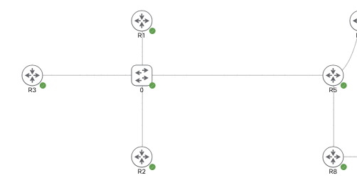
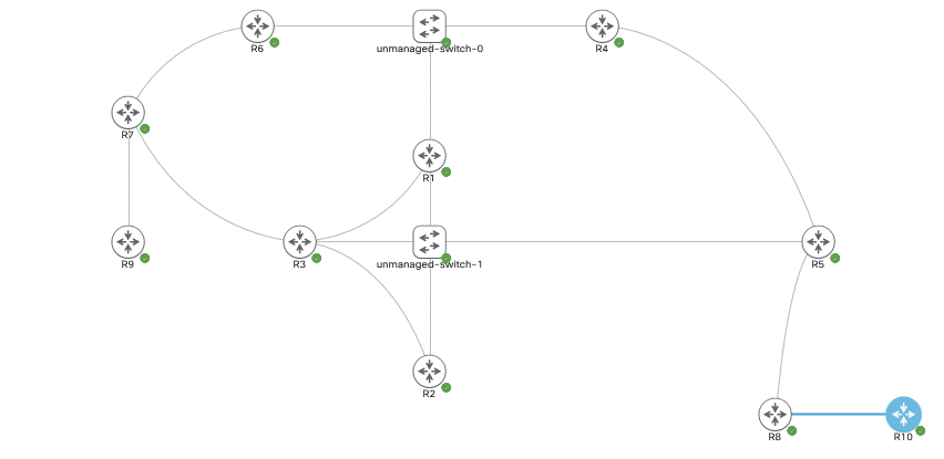
The topology currently is the one above, R1-R3 are DMVPN Phase 2 spokes and R5 is the hub. Each router is running OSPF over its tunnel 0 and advertising the loopback.

R5/Hub:
Physical IP – Gig0/0 – 96.76.43.137/29
VPN/Tunnel IP – Tu0 – 155.1.0.5
Loopback – L5 – 5.5.5.5/32

R1/Spoke:
Physical IP – Gig0/0 – 96.76.43.140/29
VPN/Tunnel IP – Tu0 – 155.1.0.1
Loopback – L1 – 1.1.1.1/32

R2/Spoke:
Physical IP – Gig0/0 – 96.76.43.138/29
VPN/Tunnel IP – Tu0 – 155.1.0.2
Loopback – L2 – 2.2.2.2/32

R3/Spoke:
Physical IP – Gig0/0 – 96.76.43.137/29
VPN/Tunnel IP – Tu0 – 155.1.0.3
Loopback – L3 – 3.3.3.3/32

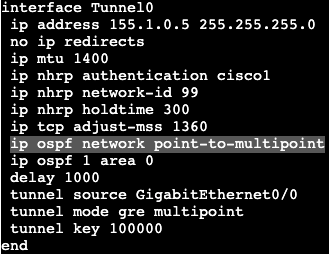
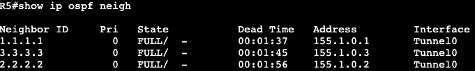
The OSPF network types are currently set to Broadcast with the hub as DR. If the network type on each tunnel interface is changed to ‘point-to-multipoint’, we’ll see that the DR/BDR process goes away.

Network type adjusted on all spokes as well as hub.

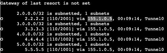
Now on a spoke if the routing table is shown, we’ll see that each spoke next hop hits the hub, unlike the broadcast network before. This is due to Next Hop Override not functioning yet.

To enable NHO, we need to add some commands. On each spoke we’ll add ‘ip nhrp shortcut’, and the hub gets ‘ip nhrp redirect’. Both of these commands are added on the tunnel 0 interface, or in general the DMVPN tunnel interfaces.

Now when doing a traceroute from R1 to R2 you can see that traffic first gets directed to the hub, then down to R2/spoke. If the traceroute is performed again though we’ll see the traffic goes directly from spoke to spoke.

Looking at the routing table of R1 shows now a % sign next to the route on R1 to R2 – 2.2.2.2, which means next hop override is taking place. Next hop does not change in the routing table but it can be seen in the cef table.

EIGRP:

OSPF has pretty big limitations in this type of topology when it comes to route manipulation via areas and summarization. If a tool like summarization were to be used, it’s much better to use BGP or EIGRP.

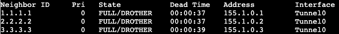
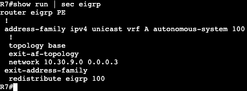
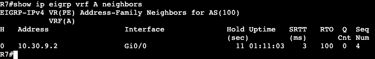
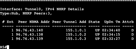
The above topology was changed to run EIGRP. We’re enabling all the same interfaces in the EIGRP process and there are three EIGRP DMVPN neighbors on the hub. Each spoke is receiving routes over the DMVPN tunnels.

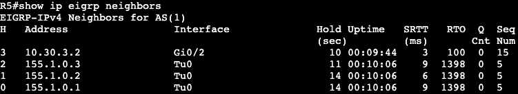
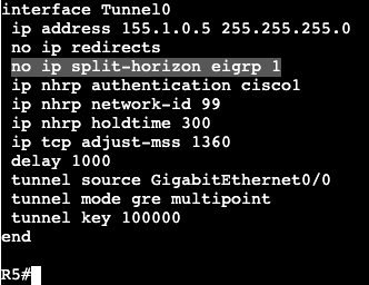
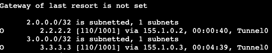
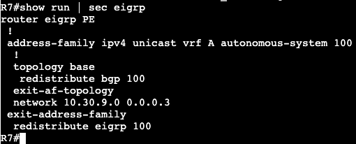
In the image directly above we’re reading the routing table for R1. Notice that it’s only receiving routes from the hub at R5. None of the routes from our other spokes, R2 and R3. That’s because the hub needs the command ‘no ip split-horizon eigrp 1’.

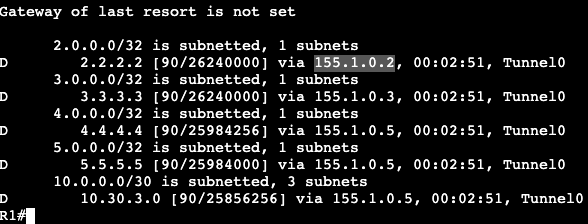
Once that’s added R1 begins receiving the routes from the other DMVPN spokes. The next hop does not change in Phase 3 however, that’s still the default behavior. In Phase 2 we’d add Next-Hop-Self, but that’s unnecessary in Phase 3 due to NHRP’s response that advises spokes to enable direct tunnels to each other.

With EIGRP enabled we can run a traceroute from R1 to R2 and we’ll see the first packet gets directed to the hub, R5. Running a traceroute again will show traffic is now going directly from spoke to spoke. In the routing table of R1 we’ll see that there’s a NHO occuring from the ‘%’, and in the cef table we’ll see that this is where that NHO is taking place.

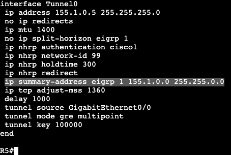
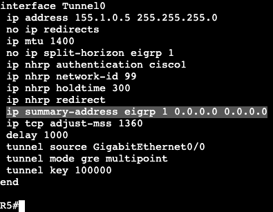
Now because this is EIGRP, we can easily do a summarization from the hub. On R5 we’ll enter the below commands and then look at a spoke routing table.
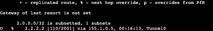
R1 Route Table:

Now from R1 a traceroute will be performed from R1’s loopback to R3’s loopback.

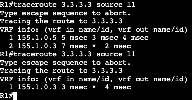
First try the packet hits the hub first. Second try it goes directly over the dynamic tunnel.

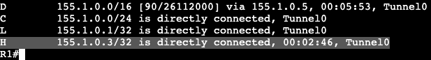
Now in the routing table of R1 a route labeled ‘H’ is visible, which means it’s from NHRP. When using summarization in DMVPN, NHRP will take care of the more specific routes when they’re needed – ie. when traffic is actually going from spoke to spoke.

Default Route:

This summarization can be done with a single default route as well. On the hub the summary address has been removed and a 0.0.0.0 0.0.0.0 has been added.

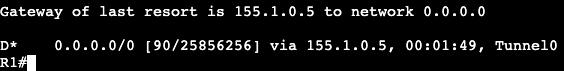
On a spoke the ‘show ip route eigrp’ now looks like below:

After pinging R2 (spoke) and looking at R1’s routing table again, we’ll see that NHRP has added another more specific route in our DMVPN topology.

DMVPN Phase 2

In the image above we are setting up DMVPN phase 2. R1-3 are spokes and R5 is the hub. Current reachability should not matter all that much because it’s one broadcast domain between the four routers. IP addresses are assigned below:

R5/Hub:
Physical IP – Gig0/0 – 96.76.43.137/29
VPN/Tunnel IP – Tu0 – 155.1.0.5
Loopback – L5 – 5.5.5.5/32

R1/Spoke:
Physical IP – Gig0/0 – 96.76.43.140/29
VPN/Tunnel IP – Tu0 – 155.1.0.1
Loopback – L1 – 1.1.1.1/32

R2/Spoke:
Physical IP – Gig0/0 – 96.76.43.138/29
VPN/Tunnel IP – Tu0 – 155.1.0.2
Loopback – L2 – 2.2.2.2/32

R3/Spoke:
Physical IP – Gig0/0 – 96.76.43.137/29
VPN/Tunnel IP – Tu0 – 155.1.0.3
Loopback – L3 – 3.3.3.3/32

The config on the hub/R5 is below:


The config on any spoke is below, minor IP changes:

On each router we’re running EIGRP AS 1 that is advertising each loopback and participating/creating adjacency on the physical interface. The main difference between the hub vs. spoke configuration are the NHS, map and map multicast commands. All of them specifying the hub/server/hub IPs.

Now on the hub we’ll see the below screen after entering ‘show dmvpn’:

The attribute D on the right means they were setup dynamically. Now looking at routes sourced from EIGRP, we receive the following from a spoke:

R1 is receiving the loopback of R5, as well as a couple routes from a router running EIGRP on the other side (outside of DMVPN) of R5. A router advertising it’s own loopback of 4.4.4.4/32.

Unfortunately we are not receiving routes from the other DMVPN spokes. This is due to EIGRP being a (hybrid) distance vector protocol that uses Split Horizon as loop avoidance. To fix this the hub will need to turn split horizon off.

After this there is a DUAL resync and the routes start to come through.

Spoke to Spoke communication:

As of right now if a spoke wants to speak to another spoke, it will first have to traverse the hub. This is due to EIGRP changing the next hop value to its tunnel 0 interface. This can be changed with the command below on R5 tun0:

‘no ip next-hop-self eigrp <process id>

Now the routes on R1 show the VPN address of each spoke as the next hop. If a traceroute is completed from R1’s loopback to R2’s loopback, the first hop shows it goes to the hub, second to the spoke. If this is performed again however it can be seen that now there’s spoke to spoke communication. In addition on R1 we’ll see with ‘show dmvpn’ that there’s a dynamic tunnel created between the two.

OSPF:

All of this can be completed with other routing protocols. EIGRP has been removed from each router and now this will be completed with OSPF.

For the spokes on each tunnel and loopback interface we’re going to enable ‘ip ospf 1 area 0’, and on the tunnel interface we will change the network type via ‘ip ospf network broadcast’.

The two commands above will be added on the hub as well, but the hub also needs the command ‘ip ospf priority 255’ under the tunnel interface. The reason for this is because we cannot have any non-hub device as the Designated Router. If a spoke becomes the DR then updates will not work because each spoke does not statically have a connection between the two devices. The hub is needed for the DMVPN spoke to spoke connectivity. Routing updates in this situation will eventually fail.

An additional command to make sure a spoke does not become the DR is by changing their priority to 0 so they take themselves out of the election process.

An ‘ip ospf priority 0’ shows that all of the spoke neighbors are now DROTHERs, so they’ll never even be a BDR.

Now on R1 when looking at ‘show ip route ospf’ we’ll see the routes for the neighbors come in. On the routes to other DMVPN spokes, we’ll see that the next hop is not modified like it was originally in EIGRP.

To reach 3.3.3.3, the next hop value is the VPN address of R3 instead of R5, the hub. This is why OSPF Broadcast network type is used. The DR process does not modify next hop. The limitation to using OSPF in DMVPN however has to do with needing to specify DR and not being able to summarize. In this scenario all routers are in area 0.

DMVPN Phases Overview

  • DMVPN Phase 1
    • mGRE on Hub and p-pGRE on spokes
      • No direct spoke to spoke communication.
    • Routing
      • Summarization and default at hub is allowed.
      • Next-hop on spokes is always changed by the hub.
  • DMVPN Phase 2
    • mGRE on hub and spokes
      • NHRP required for spoke registration to hub.
      • NHRP required for spoke to spoke resolution.
      • Spoke to spoke tunnel triggered by spoke.
    • Routing
      • Summarization/default not allowed at hub.
      • Next hop on spokes is always preserved by hub.
      • Multi-level hierarchy requires hub daisy-chaining.
  • DMVPN Phase 3
    • mGRE on hub and spokes.
      • NHRP required for spoke registration to hub.
      • NHRP required for spoke to spoke resolution.
    • When a hub hairpins out same interface:
      • Send NHRP redirect message to packet source.
      • Forward original packet down to spoke via RIB.
    • Routing
      • Summarization and default at hub is recommended.
        • Results in NHRP routes for spoke to spoke tunnel.
        • With no-summary, NHO is performed for spoke to spoke tunnel.
          • Next-hop is changed from hub IP to spoke IP.
      • Next hop on spokes is always changed by the hub
        • NHRP resolution triggered by hub.
      • Multi-level hierarchy works without daisy-chaining.

DMVPN Overview

  • What is it?
    • Point to multipoint Layer 3 overlay VPN
      • Logical hub and spoke.
      • Direct spoke to spoke supported.
    • Uses combination of the following:
      • Multipoint GRE Tunnels
      • Next Hop Resolution Protocol
      • IPSEC Crypto Profiles
      • Routing
  • Why?
    • Independent of SP access method
      • Only requirement is IP connectivity
      • Can be used with different types of WAN connectivity
    • Routing policy not dictated by SP.
      • E.g MPLS L3VPN restrictions
    • Highly scalable
      • If properly designed.
  • How?
    • Allows on-demand full mesh IPSEC tunnels with minimal configuration.
      • mGRE
      • NHRP
      • IPSEC Profiles
      • Routing
    • Reduces need for amount of tunnels required for full mesh.
      • Uses one mGRE interface for all connections.
      • Tunnels are created on-demand between nodes.
      • Encryption is optional.
        • Almost always used.
    • On demand tunnels between nodes.
      • Initial tunnel-mesh is hub and spoke (always on)
      • Traffic patterns trigger spoke to spoke.
      • Solves management scalability.
    • Maintains tunnels based on traffic patterns.
      • Spoke to spoke on demand.
      • spoke to spoke lifetime based on traffic.
    • Requires 2 IGPs
      • Underlay and overlay.
      • IPv4 and IPv6 supported for both passenger and transport.
    • Main components
      • Hub/NHRP Server (NHS)
      • Spokes/NHRP Clients (NHS)
    • Spokes/Clients register with Hub/Server
      • Spokes manually specify Hub’s address
      • Sent via NHRP Registration Request
      • Hub dynamically learns spokes’ VPN address and NBMA address.
    • Spokes establish tunnels to hub
      • Exchange IGP routing info over tunnel.
  • Spoke 1 knows Spoke2’s routes via IGP.
    • Learned via tunnel to hub
    • Next-hop is spoke2’s VPN IP for DMVPN Phase 2.
    • Next-hop is hub’s VPN IP for DMVPN Phase 3.
  • Spoke 1 asks for Spoke2’s real address
    • Maps next-hop (VPN) IP to tunnel source (NBMA) IP
    • Sent via NHRP Resolution.
  • Spoke to Spoke tunnel is formed
    • Hub only used for control plane exchange
    • Spoke to spoke data plane may flow through hub initially.
  • NHRP Messages
    • Registration Request
      • Spokes register their NBMA and VPN IP to NHS
      • Required to build the spoke to hub tunnels.
    • NHRP Resolution Request
      • Spoke queries for the NBMA-to-VPN mappings of other spokes.
      • Required to build spoke to spoke tunnels
    • NHRP Redirect
      • NHS answer to a spoke to spoke data plane packet through it.
      • Similar to IP redirects when packet in/out is same.
      • Used only in DMVPN Phase 3 to build spoke to spoke tunnels.
        • Go to next hop for spoke to spoke.

MPLS PE-CE with BGP

In the image below, we’re running MPLS L3VPN with BGP on both the provider and customer ends – ie. PE/P and CE.

ASN List:

R9/R7 – CE, ASN 1000
R10 – CE, ASN 1000
All other devices – Running ASN 100.

In this scenario the customer wants to run the same ASN on both remote ends of the MPLS L3 VPN. R10 is exchanging it’s loopback 10.10.10.10/32 across the VPN to R7 and R8, but unfortunately it’s not showing in the remote end’s routing tables.

The route 10.10.10.10/32 looks to be advertised or received all the way up to R7, where it does not show. The reason for this is due to BGP’s built in loop prevention mechanisms. If the same ASN is found in a route that’s the local ASN then the route is dropped.

AS-Override

AS-Override is the first option to fix this. The configuration is advertised outbound on R6 to R7, which will change from R7’s perspective what ASN the route 10.10.10.10 is coming from.

Under R6’s VRF Address family we add to the neighbor command.

Now on R7 we see that R10’s loopback is successfully making it to the routing table via R6.

AS-Override in general is creating another problem though in that it removes the original ASN from the path the route is advertised from. This is breaking the built in loop prevention for BGP. When AS-Override is used it allows for the route coming from R10 to get advertised back into ASN 1000 on R10’s side, creating a loop. A method of fixing this is a with a route tag called Site of Origin (SoO).

Site of origin is an extended community that throws a tag on routes routes as they’re advertised outbound. In this situation it will allow R6 and R3 to compare tags and if they match, the two routers know they have the same route and no need to advertise back to each other.

The configuration is straightforward. On R6 and R7 we’ll configure the following:

Under AF we’re specifying the soo tag (extended community) that will match on both R6 and R3. Since they match they’re aware the route does not need to be advertised to each other which would create a loop. The SoO can be seen under ‘show ip bgp vpnv4 all neighbor <neighbor address>

MPLS PE-CE Routing with EIGRP

In the topology below we’re still running iBGP between R8 and R7, and the goal is to run EIGRP as the internal customer routing protocol. We’ll be redistributing EIGRP into the BGP process that is then crossed over VPNv4.

First we’ll create EIGRP domains on each customer site. R7<–>R9 and R8<–>R10 EIGRP adjacencies will be formed in VRF A. Below will have R7 and R9 but R8 and R10 will be identical.

R9 will have a normal EIGRP configuration advertising all networks (0.0.0.0).

And R7 will have a similar configuration except it will setup the EIGRP config in VRF A

The interface connected to R9 has already been assigned VRF A and has an IP applied. Because of this the neighbor adjacency comes up. Note- we’re not creating an adjacency with R3 which is part of the P network, hence the smaller network statement on R9, our PE.

The adjacency can be seen with a ‘show ip eigrp vrf A neighbor’.

The configuration for iBGP over the MPLS domain is already setup between R7 and R8, and that can be seen with a simple ‘show ip bgp summary’. In addition, our VRF already has the Route Distinguisher and Route Targets imported and exported, as seen below:

So now to advertise EIGRP routes over the BGP tunnel, we just need to redistribute between the two routing protocols.

EIGRP into BGP:

BGP into EIGRP:

Note this needs to be completed under ‘address-family ipv4 vrf A’.

Now- when checking the global routing table of R10 (across iBGP and MPLS domain), we see that the Loopback for R9 is in the routing table.

This can also be seen from the BGP VPNv4 table – ‘show ip bgp vpnv4 all’

Note- these routes are showing up as internal routes instead of external for both routing protocols.

For EIGRP this allows feasibility condition to be spread across sites.

MPLS L3 VPN Troubleshooting

  • Is LDP Enabled?
    • ‘show mpls interfaces’
  • Is LDP Transport working?
    • ‘debug mpls ldp transport events’
  • Is LDP session authenticated?
    • Like BGP, LDP uses TCP auth (option 19)
  • Are labels actually bound?
    • ‘show mpls ldp binding’
    • ‘show mpls forwarding-table’
    • ‘debug mpls ldp binding’
  • Is allocation being filtered?
    • Advertise filter vs. allocate filter.
    • Typically only /32 needs an allocation.
  • PE-CE Routing
    • Is loop prevention being violated?
      • OSPF down-bit and domain-tag.
      • BGP AS-path and Site-of-Origin (SoO)
      • EIGRP Site-of-Origin
    • VRF Hung
      • ‘clear ip route vrf *’
      • Forces re-import/export
  • VPNv4 BGP
    • Is RT being filtered?
      • Wrong import/export policy
      • Default route target filter
      • VPNv4 Route Reflection
  • MPLS Data Plane
    • Is VPNv4 peering to a /32?
      • Problems in PHP
        • The last label will be popped early.
      • Problems in route summarization.
    • Are LDP and IGP synced?
      • LFIB can only install label for RIB/LRIB intersection.

MPLS Verification

  • Complete Components:
    • Core IGP/LDP on PE and Ps
      • ‘mpls ldp autoconfig’ under OSPF process for example.
    • VRF PE to CE
    • PE to CE Routing
    • VPNv4 BGP between PEs.
    • VRF to VPNv4 Import/Export
    • Data Plane
  • Core IGP/LDP
    • Did LDP ‘Tunnels’ properly form?
      • ‘show mpls interfaces’
        • This command will not show loopback interfaces, but the loopback needs to be advertised into IGP for these LDP tunnels to form.
      • ‘show mpls ldp neighbor’
      • ‘show mpls ldp binding’
        • Displays exact label data for specific path.
  • Core IGP/LDP continued….
    • Is there an LSP between PE /32 Loopbacks?
      • ‘show mpls forwarding-table’
      • ‘show ip cef’
      • ‘traceroute’
        • Important there’s a full path via loopback interfaces.
  • VRF PE to CE
    • ‘show <ip> vrf’
    • ‘show <ip> vrf detail’
    • ‘show run vrf’
  • Were interfaces properly allocated to the VRF?
    • ‘show ip route vrf *’
    • ‘show ipv6 route vrf *’
  • VPNv4 BGP Between PEs
    • ‘show bgp vpnv4 unicast all summary’
    • ‘show ip bgp vpnv4 all summary
  • Are extended communities being sent?
    • ‘debug bgp vpnv4 unicast updates’
  • VRF to VPNv4 import/Export
    • ‘show <ip> vrf detail
    • ‘show run vrf’
  • Did IGP to BGP redistribution occur?
    • ‘show bgp vpnv4 unicast all’
    • ‘show ip ospf database’
    • ‘show ip eigrp topology’
  • Are VPNv4 routes being sent/received?
    • ‘show bgp vpnv4 unicast all’
    • ‘show bgp vpnv4 unicast all neighbor advertised-routes’
    • ‘clear bgp vpnv4 unicast * [in|out]’
  • Data Plane
    • CE commands are normal global
      • Ensure verification comes from correct source
      • PE-CE link might not be exported into VPNv4.
    • PE Commands VRF aware
      • ‘ping vrf’
      • ‘traceroute vrf’
      • ‘telnet vrf’

MPLS L3 VPN Configuration

  • PE-CE Routing
    • No MPLS Required
    • Normal IPv4 and IPv6 routing
    • All IPv4 protocols supported.
    • Some IPv6 protocols supported.
  • MPLS Core (P and PE) Devices
  • IGP + LDP
    • goal is to establish LSP between PE /32 Loopbacks.
    • Traceroute between loopbacks for verification.
  • Other label switching mechanisms are available but outside of CCIE Scope.
    • BGP + Label, RSVP-TE
  • MPLS Edge (PE) devices
    • VRF
      • VRF aware PE-CE Routing
      • Used to locally separate customer routes and traffic.
    • VPNv4 BGP
      • iBGP peering to remote PE /32 Loopbacks.
      • Separates customer control and data plane over MPLS core.
      • Other designs supported outside scope of CCIE.
        • VPNv4 RR, Multihop EBGP VPNv4, etc.
    • Redistribution
      • VRF to BGP import and export policy
  • VRF
  1. Create a VRF name that’s unique to the box.
  2. Then we’re creating a Route-Distinguisher that makes the prefix unique.
  3. Then we’re defining the Route-Target import and export policy.
    1. ie – anything in VRF A being advertised into BGP is getting the extended community added to it of 100:1, which is then getting advertised with a modified IPv4 prefix. An IPv4 VPN prefix.
      1. ie. export.
    2. The other way around, anything that comes into this router with a route-target of 100:1 will be imported into VRF A.
      1. ie. import.
  • VPNv4 BGP

The command ‘neighbor 7.7.7.7 send-community extended’ allows us to send the route target extended community option. The command is also enabled by default after we run the activate command.

  • Redistribution

May be needed if the customer is using IGP like OSPF but needs their WAN routes added into their internal routing domain. If the CE is running BGP to the PE however, then redistribution obviously not needed.

MPLS L3 VPN

  • How it works?
    • Separation of customer routing information.
      • VRF
      • Different customers have different routing tables.
      • IGP/BGP run inside the VRF between the customer and SP.
    • Exchange of customer’s routing info inside SP.
      • MP-BGP through the SP network.
      • Traffic is label switched towards BGP next-hops.
  • VRF Lite vs. MPLS VPNs
    • In VRF Lite all devices in transit path must carry all routes in all VRF tables.
    • In MPLS VPNs only PE routers need customer routes
    • Accomplished via the following:
      • VPNv4 BGP
        • Route Distinguisher + Prefix makes VPN routes globally unique.
      • MPLS VPN Tag/Label
        • P routers only need to know how to reach BGP next-hop.
        • BGP free core logic.
  • High Level
    • Establish Label Switched Path (LSP) between PEs.
      • IGP and LDP
    • Exchange routes with customer.
      • PE-CE IGP or BGP
    • Exchange customer routes between PEs.
      • iBGP and MPLS VPN labels
    • Label Switch from PE to PE.
      • Data follows the IGP and LDP transport label.
  • Multi-protocol BGP
    • How do PE routers exchange VRF info?
      • RFC 4364 MPLS IP VPNs
    • MP-BGP Defines AFI 1 and SAFI 128 as VPN-IPv4 or VPNv4
      • 8 byte Route Distinguisher (RD)
        • Unique per VPN or per VPN site.
        • ASN:nn or IP-address:nn
      • 4 byte IPv4 address
        • Unique per VPN
      • Implies globally unique routes.
    • VPNv4 includes MPLS VPN label
  • NLRI Format
    • VPNv4 NLRI main attributes include…
      • 8 byte RD
        • Unique per VPN or per VPN site.
        • ASN:nn or IP-address:nn
      • IPv4 prefix and length
        • Unique per VPN because of RD
      • Next hop
      • MPLS VPN label
    • Regular BGP attributes stay the same.
  • VPNv4 Routes
    • Route Distinguisher used solely to make route unique.
      • Allows for overlapping IPv4 addresses between customers.
    • New BGP extended community ‘route-target’ used to control what enters/exits VRF table.
      • export route-target
        • What routes will go from VRF into BGP
      • import route-target
        • What routes will go from BGP into VRF
    • Allows granular control over what sites have what routes.
  • Route Distinguisher vs. Route Target
    • Route Distinguisher
      • Makes route unique
      • Only one RD per VPNv4 route.
    • Route Target
      • Controls the route’s VPN memberships
      • Can be multiple RTs per VPNv4 route.
  • Route Target
    • 8 byte field
      • RFC 4360
    • Format similar to route distinguisher
      • ASN:nn or IP-address:nn
    • VPNv4 speakers only accept VPNv4 routes with a route-target matching a local VRF
      • Some exceptions, eg. route-reflectors.
    • VPNv4 routes can have more than one RT
      • Allows complex VPN topologies.
      • Full mesh
      • Hub and spoke
  • Transport label vs. VPN label
    • L3VPN needs at least 2 labels to deliver traffic.
      • can be more with applications like MPLS TE, FRR, etc.
    • Transport label
      • Tells SP core routers which PE traffic is destined for.
        • Who is exit point.
      • Typically derived from LDP
        • Sometimes called IGP label.
    • VPN Label
      • Tells PE router which CE traffic is destined for.
      • Derived from VPNv4 advertisements of PEs.
    • In general, VPN label used for final destination/VRF connectivity and Transport label used for label switching through SP core.