OSPF Adjacencies, Network Types

  • OSPF has multiple network types that need to be compatible in order to form OSPF adjacencies.
  • Most common in Enterprise are Point-to-Point and Broadcast/Multiaccess.
  • When troubleshooting an OSPF adjacency issue, check on both ends that the interface network types are setup the same.
    • Default is broadcast/multiaccess
      • Will include DR/BDR election
    • Point-to-Point
      • Expects there to be a single adjacency/single OSPF speaking node.
    • Point-to-Multipoint
      • Needed on specific hub and spoke network types, like DMVPN.
      • The Hub will need this command to form adjacencies with multiple spokes. Each spoke will be configured as point-to-point.

Configuration of network types is done on the interface level.

  • Normal Broadcast/Multiaccess:
    • No specification in config, default.
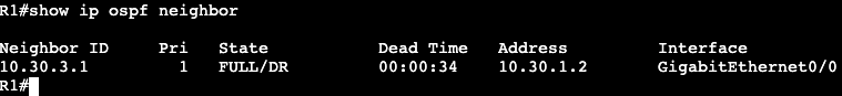
    • ‘show ip ospf neigh’ will show a DR/BDR/DROTHER relationship.
  • Point-To-Point:
    • ‘R5(config-if)#ip ospf network point-to-point’
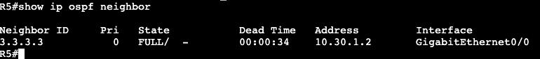
    • ‘show ip ospf neigh’ will show a Full adjacency without the DR/BDR/DR
  • Point-To-Multipoint
    • ‘R5(config-if)#ip ospf network point-to-multipoint’
    • Point to Multipoint will change the OSPF timers on the interface to something that’s different than the default for Broadcast/Multiaccess and Point-to-point.
      • If using point-to-multipoint with Broadcast/Multiaccess or point-to-point, the hello timers will need to be changed on one of the sides to match.

The image below shows two routers running OSPF. R5 is operating in point-to-multipoint, and R3 is running in normal broadcast.

Running a ‘show ip ospf int gig0/0’ shows that R5’s interface is running in point-to-multipoint and it’s timers are 30, 120, 120.

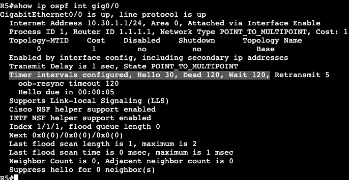
The router R5 is trying to form an adjacency with is running in normal broadcast mode, which sets the Hello timer to 10, 40, 40.

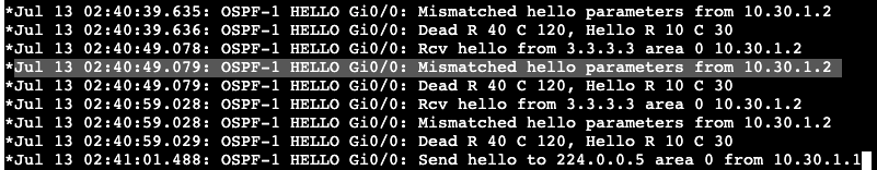
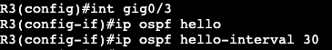
Adding a ‘debug ip ospf hello’ and bouncing R5’s interface shows the problem as well. What needs to be configured are the hello timers on R5 or R3 to match. On R3 the below command was added and the adjacency came up between broadcast and point-to-multipoint networks.

Above we can see the intervals were changed on R3’s interface, and below the adjacency shows with a much higher dead time than the default 10 seconds in a broadcast or point-to-point network.

This example in general is a bit odd because it’s forming an adjacency between a Broadcast network and a point-to-multipoint. It doesn’t appear as if it should actually be working. When I changed the hello interval to match on both sides, the adjacency came up. When I tried exchanging routes I could not get it to work. Then I took the adjacency down and could not get it to form again until I set the broadcast to point-to-point. Routes began exchanging between both nodes as well. In general the timers change is still valid though. The hello interval would have had to be changed if I was working with a point-to-point network type the entire time.

Correction – The Point-to-Multipoint and Broadcast network types are not compatible. Compatibility depends on whether the LSA Type 2 (DR/BDR) is being used. Type 2 is used in broadcast and not in Point-to-Multipoint.

OSPF Single Area

Configuration:

  • Enable Globally
    • ‘router ospf <process id>’
    • Network statements with IPs/wildcard masks
      • ‘network 0.0.0.0 0.0.0.0 area <area #>
  • Enable Under Interface
    • ‘ip ospf <process id> area <area #>
    • If a manual router ID is needed, needs to be entered under the ‘router ospf <process id>’ configuration.
    • This enables OSPF for both primary and secondary IP addresses.
    • OSPF stays enabled even when IP address changes.
  • Verification basics:
    • ‘show ip ospf’
    • ‘show ip ospf int brief’
      • Quick way of showing which interfaces are enabled, which area each interface is in.
    • ‘show ip ospf neighbor
    • ‘debug ip ospf adjacency’
    • ‘show ip ospf database’

Below there are two routers running OSPF.

R2:
– Gig0/0 – 10.30.1.2 255.255.255.252
– L0 – 10.30.2.1 255.255.255.0
– L2 – 10.30.3.1 255.255.255.0

R1:
– Gig0/0 – 10.30.1.1 255.255.255.252
– L0 – 172.16.1.1 255.255.255.0
– L1 – 172.16.2.1 255.255.255.0

R1 OSPF Config:

R2 OSPF Config:

R1 Verification/Routing Table:

R2 Verification/Routing Table:

General OSPF

  • IPv4 – RFC 2328 v2
  • IPv6 – RFC 5340 v3
  • Uses Shortest Path First Algorithm.
  • Guarantees a loop free topology by using SPF and Area 0.
  • Standards
    • Can be used by multiple vendors.
  • Convergence
    • Very Fast
    • Tracks Neighbor adjacencies actively.
    • Event driven incremental updates.
  • Efficient updating
    • Non-OSPF updates do not process the updates on link.
    • Uses multicast and unicast for updates.
  • Link metrics are based upon bandwidth of interfaces.
  • Security
    • Supports clear text, MD5, SHA, IPsec for authentication.
  • Extensibility
    • Application support through ‘opaque LSA’

OSPF Operations:

  • Step1:
    • Uses Hello packets to find neighbors on links.
    • Protocol 89
    • Sends information via multicast
      • 224.0.0.5 – all OSPF speaking routers
      • 224.0.0.6 – DR/BDR communication
    • Hello packets have data that both speakers must agree upon to form adjacency
    • agreement and adjacency has formed, OSPF database gets exchanged between both parties.

Adjacency Attributes:

  • Router-ID
    • Chosen via manual configuration, highest active loopback IP, then highest active interface IP.
  • Interface IP addresses
    • OSPFv2 will use the interface primary IP (IPv4)
    • OSPFv3 will use the interface link local IP (IPv6)

Attributes that have to match:

  • Area
  • Hello and dead timers
  • Network address (between two nodes)
  • Interface MTU
  • OSPF network type
  • Authentication

Hellos:

  • Sent out every hello interval (timer)
  • Contains the following data
    • RID
    • Area
    • Subnet mask
    • Interface priority
    • Hello and Dead timers
    • Authentication information
    • DR/BDR addresses
    • RID of other neighbors on the link

Adjacency States

  • Down
    • No hellos have been received.
  • Attempt
    • Hello has been sent to neighbor, nothing received back.
  • Init
    • Received hello, no acknowledgement of hello that’s been sent.
  • 2-Way
    • Have received neighbor hello and acknowledgement of local hello already sent out.
  • ExStart
    • Beginning of adjacency
    • Higher router ID is master and chooses DB sequence number
  • Exchange
    • Link state database sent through DBD packets.
  • Loading
    • Link state requests sent to ask for more info about particular LSA.
  • Full
    • Adjacency has formed, DBs are synchronized.

  • Step2:
    • Beginning of path selection.
    • Each LSA includes a cost attribute for each link.
    • Paths added to RIB are paths with lowest cost end to end.
    • ECMP is allowed.
    • Default cost value is 100Mbps / link bandwidth.
      • For bandwidth 10Gbps and higher, the reference bandwidth command needs to be used.
  • Step3:
    • Neighbor tracking is from here on out completed via hellos and LSAs
      • Hellos for tracking neighbor changes.
        • HelloInterval is what defines how often hellos are sent out for tracking. 10 and 30 seconds depending on network/interface type.
        • DeadInterval
          • Time router declares neighbor dead if it does not receive a hello.
      • LSAs for tracking topology changes.
        • If new LSA is received, the LSDB sequence number, Age, and checksum are compared to make sure everything is up to date.
        • When change occurs, LSAs are flooded out all OSPF speaking interfaces – no split horizon. Self-originated LSAs are just dropped.

EIGRP and IPv6

  • Uses protocol 88
  • Uses both Multicast and Unicast
    • Multicast FF02::A
    • Unicast to link-local
    • Multicast can be disabled
      • neighbor to link-local address

Configuration Classic Mode:

  • Enabling IPv6
    • ‘ipv6 unicast routing’
    • Valid router ID must exist.
      • Uses IPv4 format
      • If there are no IPv4 interfaces then the ID needs to be specifically stated.
        • ‘eigrp router-id’
  • Enabling EIGRP with ipv6
    • ‘ipv6 router eigrp <AS>’
    • enable global process
      • ‘no shut’ under eigrp process.
  • Enable EIGRP on link level
    • ‘ipv6 eigrp <AS>
  • If ipv6 is not enabled on the interface, that also needs to be turned on.
    • ‘ipv6 enable’
    • The adjacency will form with link-local addressing between two nodes.

Configuration Named Mode:

  • Enabling IPv6
    • ‘ipv6 unicast routing’
    • ‘router eigrp <name>’
    • Enable Address Family
      • ‘address-family ipv6 unicast autonomous-system <AS>
      • Does not need to match IPv4 AS
      • Process starts automatically on each interface.
        • To disable EIGRP on an interface, must be shutdown under af-interface.

Named mode is preferred – syntax is unified between both address families.

EIGRP Route Filtering

  • EIGRP is a distance vector routing protocol.
  • The entire EIGRP topology is not known by each speaker like in Link State.
    • This means filtering and summarization can occur on any node in the network.
  • Methods:
    • Distribute Lists, with Route-Maps
    • AD
    • Passive Interface
    • Distribute
    • Route Tags
    • Per Neighbor Prefix Limits

Distribute List Filter:
– Done with access-list and applying via distribute-list in topology base or router eigrp <as>

Access list matching prefix being filtered.
Access list applied as ‘distribute-list’ under topology base in EIGRP Named Mode
Access list applied as ‘distribute-list’ under router eigrp in EIGRP Classic Mode

Same can be done with an IP prefix list as well. With the distribute-list command the name of the IP prefix list will be used instead of an access-list number. A prefix list will give more control over bit boundaries with the ge (greater than) or le (less than) option.

Administrative Distance:
– Setting the distance to 255 can stop routes from coming into routing table.
– In EIGRP this can be set under topology base.

First step is creating an access-list that matches the prefix that’s being filtered.

Then under topology base in EIGRP, setup the distance command.

255 is what the administrative distance value. 0.0.0.0 is the source, in this case we’re saying that route coming from anywhere. 255.255.255.255 is the wildcard for the source, and 2 is referencing the access list created.

Route Map with Tag:

Routes can be modified or labeled with a tag by using a route map set statement. This can then be used to filter or modify downstream via the tag value. Example below.

First step is to create a prefix list matching the prefix that’s going to be tagged.

Then a route map needs to be created that references the prefix list and uses the set tag option. In this example the tag is being set to 10.

The ‘route-map TAG permit 20’ is needed at the bottom to allow all other traffic to pass. There’s always an implicit deny at the end of each route map.

Next step is adding the route map to the EIGRP process.

TAG is the name of the route-map created, in is the direction we’re applying the route map, and Gig1 is the interface.

Now when doing a show ip route 3.3.3.3, there’s a tag value being applied.

The same tag value can be seen now on routers BranchA is advertising to downstream.

Branch 10A, downstream router from BranchA

All of these features makes EIGRP very flexible. These types of route filtering and modification in other routing protocols often can only be completed during redistribution or when hitting an area border.

EIGRP Stub

  • Method to contain QUERY domain.
  • Good design option for DMVPN spokes.
    • Or hub and spoke topologies in general.
  • At a remote branch/location often times there’s only has one primary mode of transit back to the enterprise network. If the remote branch is setup as a regular EIGRP router, then every time there’s a topology change, anywhere, the remote branch router will receive a query from its neighbor (probably hub) asking if it knows the downed prefix. A stub EIGRP router will never receive these queries because it is assumed there’s no other EIGRP speaker behind the branch/spoke gateway.

Configuration is very simple. In Named Mode it’s under the Autonomous System.

In Classic Mode it’s under ‘router eigrp <as>’.

Note advertising connected and summary is default.

EIGRP Leak Maps

  • When advertising summary in EIGRP, a leak map can be used to throw in a more specific prefix if needed.
  • Can be used for traffic engineering.
  • Applied to a router via route map.

Configuration:

Prefix List

Route Map

EIGRP Summary Statement with Leak Map

The command ‘summary-address 10.20.0.0 255.255.0.0 leak-map leakmap‘ summarizes the 10.20.0.0 loopback IP addresses, and leaks the more specific 10.20.1.0/24 address to the EIGRP neighbor. The EIGRP neighbor’s routing table now looks like below:

EIGRP Summarization

  • Used specifically to minimize QUERY message domain
  • QUERY domain containment
    • Summarization
    • Stub router advertisement
  • QUERY message
    • Generated when route becomes Active
      • Active meaning node is asking if there’s another route to a destination.
      • Link loss
  • Auto Summary
    • Classful summarization
  • Manual Summary
    • Classless, defined by operator.
    • Supports any bit boundary.
    • Automatically suppresses subnet advertisements.
    • Can advertise subnets through leak-mapping.
    • Classic EIGRP
      • ‘ip summary-address eigrp’ under interface
    • Named EIGRP
      • summary-address at af-interface
  • EIGRP summaries are not hierarchical.
    • Can be done anywhere unlike OSPF.
  • Below is a config for EIGRP Named Mode:

Instead of going to the physical interface configuration, it’s all done in the address family af-interface config. On router R1, there’s a Loopback interface that has a /32.

But the EIGRP neighbor, R2, is receiving a /16 route to the loopback now.

  • Summary routes inherit metrics from the longer prefixes/subnets.
    • Will use the best metric.
      • Change of the best metric means the summary will be re-advertised.
      • summary-metric can help fix this.

EIGRP Authentication

  • Types of Auth:
    • MD5
    • HMAC-SHA256
  • SHA
    • Only EIGRP Named Mode
    • No Key chains
    • SHA uses static key
  • MD5
    • Both EIGRP Named and Classic Mode
    • Uses key chains
    • Supports auto key rotation.
  • Key chain supports multiple key numbers.
    • Router always sends lowest key.
    • Rotation of keys is done by defining the validity.
  • Configuration Classic EIGRP:
    • Authentication mode setup on interface
      • ‘ip authentication mode eigrp <AS> md5’
      • ‘ip authentication key-chain eigrp <AS><Key>’
      • ‘accept-lifetime’
        • How long key is valid to be received.
      • ‘send-lifetime’
        • When is key valid to be sent.
  • Configuration EIGRP Named:
    • Use of MD5 or SHA is under af-interface.

EIGRP Routes/Load Balancing

  • Feasibility Condition:
    • Used for selecting backup paths.
    • Pre-computed during DUAL
      • Advantages
        • Sub-second re-convergence when successor fails.
        • Fault isolation.
          • No need to speak with neighbors about additional paths.
        • Unequal cost distribution.
    • What the process is doing:
      • Find best path, hold onto local metric.
      • Find second best path.
        • Any router with metric lower than mine, they’re closer to destination.
        • Any router with metric equal or higher than mine, forget about them.

  • Successor – Best Path
  • Feasible Distance – Metric of Successor
  • Reported Distance – Metric of neighbors
  • Feasible Successor – Backup paths that meet Feasibility Condition
  • Only Feasible Successors can be used for unequal cost load balancing

Reconvergence:

  • If no FS:
    • Sends route into Active state
    • Sends QUERY to all neighbors
    • Reconverges from neighbor REPLY
  • With FS:
    • No route Active
    • FS promoted to Successor
    • QUERY not generated
    • Results in sub-second convergence

Bandwidth and Delay

  • Bandwidth
    • DUAL uses the lowest bandwidth along a path to a destination.
    • By prefix.
  • Delay
    • DUAL uses delay by adding up hop by hop to destination.
    • Can be modified under interface with ‘delay’ command.

Unequal Load Balancing:

  • Only Feasible Successors allowed.
  • Controlled with Variance command.
    • FD * variance > FS, load balancing happens.
  • Commands:
    • router eigrp <name>
      • address-family ipv4 autonomous-system <AS #>
      • topology base
      • variance <variance multiplier>