- Standard IP route forwarding is based off of destination and next hop.
- Policy Based Routing:
- Can be based off of multiple criteria, such as source, destination, protocol type, and source interface.
- In Cisco this is matched with a route map.
- Permit uses policy routing and deny uses normal routing table forwarding.
- Action defines what the policy is doing.
- ‘debug ip policy’ can be used to verify and troubleshoot.
- Can be applied with incoming and locally originated traffic.
Blog Feed
IP SLA
In networking when adding a static route to a router, the static route will make its way into the RIB and FIB if the router can reach the next hop and knows which interface to go out towards its destination. In theory, if the next hop becomes unreachable then the static route is removed from the active routing table until that next hop comes back. This does not work however if there’s an intermediary device in that layer 2 broadcast domain.
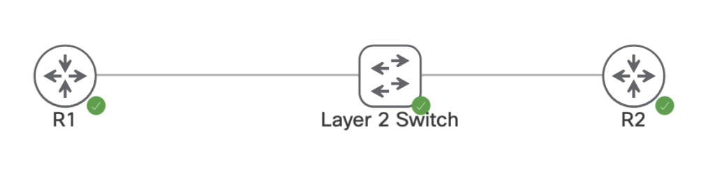
On the devices above we have the following interfaces, IPs, and static route.
R1:
Interface IP: 96.76.43.138/29
ip route 150.1.4.4/32 96.76.43.139
R2:
interface IP: 96.76.43.139/29
Interface Loopback0: 150.1.4.4/32
L2 Switch:
Nothing, all layer 2
Currently R1’s route table shows the static route is valid and the router can ping R2’s transit interface.
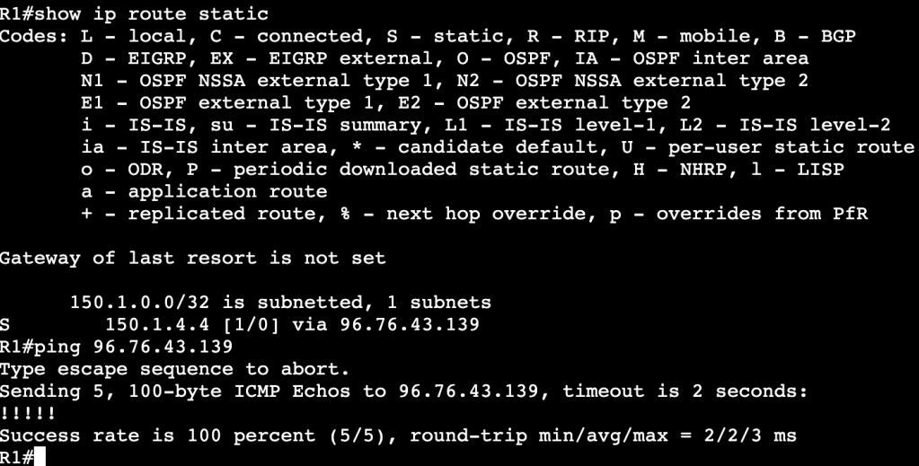
When R2’s interface is set admin down unfortunately R1’s static route does not leave the routing table, even though the next hop is no longer reachable.

This is because the layer 2 device in between is keeping R1’s interface alive. One way of fixing this is with IP SLA. We’ll configure an IP SLA agreement statement that continues to ping R2’s interface, and when the ICMP echo fails, we’ll schedule R1 to remove the static route.
Configuration:

The first part of the simple IP SLA configuration is adding the IP SLA statement with ‘ip sla 1’. It’s using icmp-echo to R2’s transit IP address. And the start time is now with a lifetime of forever. Once this.
Once that’s completed a tracking object needs to be created. The track statement has the number 1 and its associated with IP SLA1. After this is configured a console message will show onscreen saying the the IP SLA has gone from down to up.
The tracking statement needs to now be associated with the static route in R2’s routing table. That can be done with the below command(s):
no ip route 150.1.4.4 255.255.255.255 96.76.43.139 track 1
ip route 150.1.4.4 255.255.255.255 96.76.43.139 track 1
First the old route statement needs to be removed, then the new route with tracking gets enabled.
Below is an image of the route table before R2’s interface is shutdown:
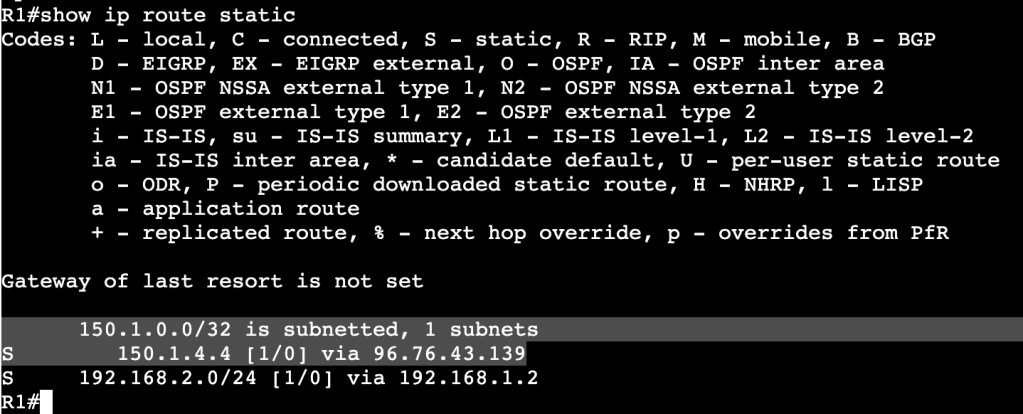
And after R2’s interface is shutdown:

A message above shows the IP SLA 1 state went down. In the route table there is now an entry for the R2 loopback but over another route with a higher administrative distance.
Multiple Spanning-Tree Protocol-802.1Q-2005
- Removes tie between VLANs and Spanning-Tree instances.
- Needed when reaching the max limit of VLANs, because the switch will not support that many STP instances.
- MST Region:
- Bridges that all agree upon instance name, revision number, and VLAN to STP instance mappings.
- Intra Region
- Within Region, details are known.
- VLAN to STPIs are manually defined.
- Undefined VLANs fall into CIST/MST0
- Inter Region
- Information between regions is not known.
- Regions see each other as virtual bridges.
- Simplifies Inter-Region calculation.
- Intra-Region MSTIs collapsed into CIST.
- Configuration:
- Requires Region name, Revision Number, VLAN to instance mapping
- Enable MST globally.
- Commands:
- ‘spanning-tree mst <instance> priority’
- ‘spanning-tree mst <instance> root <primary/secondary>’
- ‘show spanning-tree mst <instance>’
- ‘show spanning-tree root’
- Enabling:
- ‘spanning-tree mode mst’
- ‘spanning-tree mst configuration’
- ‘name REGION0’
- ‘instance 1 vlan 1-10’
- ‘instance 2 vlan 11-20’
- The root bridge must be in the MST instance, otherwise instance will fail.
- Backwards Compatibility:
- When running RSTP or PVST alongside MST, a show spanning-tree will provide ‘Bound’ ports.
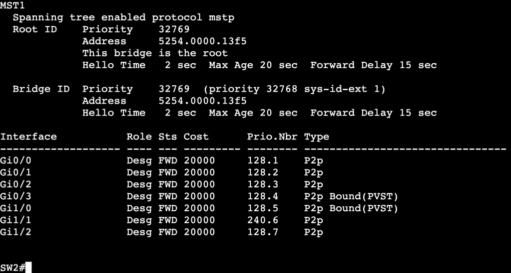
- Ports Gi0/3 and Gi1/0 are connected to a device running PVST. This works though because the root bridge for VLAN 10 is in the MST region.
- All commands are the same when using RSTP and MST, but instead of using ‘vlan’, we use ‘mst’ and region number/name.
Rapid Spanning-Tree Protocol – 802.1D-2004
- Differences from legacy STP
- Rapid convergence due to sync process.
- Simplifies port states.
- Additional port roles.
- Port States:
- Discarding
- Drops frames
- Learning
- Dropping frames but builds CAM table
- Forwarding
- Normal Forwarding
- Discarding
- Roles:
- Root/Designated same as legacy STP
- New:
- Alternate
- Same as UplinkFast in regular STP.
- Upstream interface that’s less desirable to root.
- No need to configure UplinkFast, just part of RSTP.
- Immediately begins forwarding upon root port failure.
- Backup
- Backup downstream facing interfaces.
- Activates if primary designated port fails.
- Normal state is discarding.
- Only seen in shared segments – ie. hubs.
- Edge
- Same as STP PortFast ports.
- No Topology Changes, immediately begins forwarding.
- Alternate
- Link Types:
- Point to Point – Full Duplex
- Shared – Half Duplex
- Sync process only occurs on point to point Designated ports.
- RSTP Sync Process:
- Process of non-Root Bridge to sync root port with rest of topology.
- After root port selected, all non-edge ports are considered designated.
- Bridge then sends out proposals with root bridge info – port costs, etc.
- Downstream bridges review and either agree or send alternate info.
- Sending additional info means downstream switch thinks it has better path to root bridge.
- SYNC PROCESS MAKES SURE ALL RSTP SPEAKERS AGREE ON ROOT PORTS AND DESIGNATED PORTS.
- Enabling Edge ports is important because it decreases the amount of churn when sync process is occurring. Edge ports do not partake in Syncronization.
- Failure Detection:
- In STP, BPDUs are only sent out by Root Bridge
- In RSTP, BPDUs are generated by every RSTP speaker via Hellos – 2 second default.
- Reconvergence begins after 3 hellos are missed.
- MaxAge is used for backwards compatiblity with STP.
- Convergence:
- When root port failure occurs, the Alternate port takes over.
- New root is synced down to all bridges.
- If no alternate port is available, the bridge declares itself as root bridge, synchronizes, then adapts if there is better info.
- Slow convergence can happen with large meshy topologies.
- When root port failure occurs, the Alternate port takes over.
- TCN:
- Generated after link goes into forwarding state.
- Originates from switch that detects event.
- Floods via reverse path forwarding.
- Causes unicast traffic flooding.
General Spanning-Tree Protocol
- Order of Operations:
- Elect the root bridge.
- After a root bridge has been selected, all of it’s ports will be set into designated ports that are forwarding downstream.
- Select root bridge interfaces.
- Each non-root switch will look through ports and elect a root port that is pointed at the root bridge.
- All other ports will be elected as designated ports that are pointing further downstream.
- All ports not in designated will be in blocking.
- Elect the root bridge.
- Root Bridge Election:
- Lowest Bridge ID wins.
- Bridge ID contains:
- Bridge priority (0-61440)
- System ID (0-4095)
- MAC address
- Bridge ID contains:
- Lowest Bridge ID wins.
- Changing Root Bridge Election:
- Change bridge priority manually
- ‘spanning-tree vlan <vlan id> priority <priority number by 4096>
- Use root bridge command
- ‘spanning-tree vlan <vlan id> root <primary or secondary>
- Will set local priority based on current Root Bridge priority
- ‘show spanning tree root’ will show which switch is root.
- Change bridge priority manually
- Root Port Election:
- Root Port is upstream pointing towards the Root Bridge.
- Selected as RP based on lowest path cost (all link costs added up)
- Higher bandwidth = lower cost – ie. Fa is 19, 1Gbps is 4
- When a cost tie occurs:
- Lowest upstream bridge ID
- Lowest upstream port ID
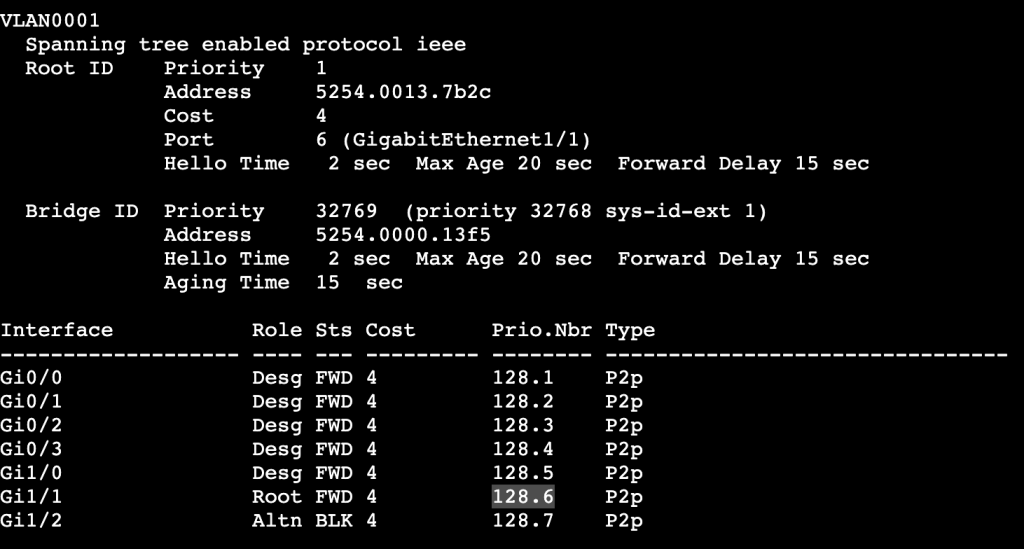
- Root Port priority:
- Per above, lowest wins.
- Root Port priority can be changed locally, which will then impact the downstream switch.
- Image above shows root port as Gi1/1 to SW1. If Gi1/1 receives the following config, then the root port is changed to Gi1/2 instead:
- switch(config-int)#spanning-tree port-priority 240
- Image above shows root port as Gi1/1 to SW1. If Gi1/1 receives the following config, then the root port is changed to Gi1/2 instead:

- ‘show spanning-tree vlan <id> detail’
- Will display the local and remote port IDs.
- Useful for modifying traffic flow in bridging domain.

- Changing paths when not changing which switch is Root Bridge.
- switch(config-int)#spanning-tree vlan <#> cost <#>
- Command above will change the link cost locally on a switch.
- By adding all link costs up towards the bridge, we can modify which port is a root bridge locally.
- Changing paths can be done with the bandwidth command as well.
- Bandwidth is connected to STP cost.
- switch(config-int)#spanning-tree vlan <#> cost <#>
- Plain Spanning Tree Protocol timers
- Hello – How often BPDUs are sent out interfaces.
- Defaults to 2 seconds
- MaxAge – How long to wait in blocking without a BPDU
- Defaults to 20 seconds.
- Forward Delay – How long to wait in listening and learning
- Defaults to 15 seconds
- Hello – How often BPDUs are sent out interfaces.
- PortFast
- Bypasses Forwarding Delay
- For ports not running spanning tree
- ‘switch(config-if)#spanning-tree portfast’
- UplinkFast
- Legacy for ‘Alternate port’ when root port dies.
- Automatically switches alternative port to forwarding when root goes down.
- ‘switch(config)#spanning-tree uplinkfast’
- Automatically changes all port priorities when root port dies.
- Way to tell all other switches that it is not the root.
- BackboneFast
- Indirect failures should start recalculating immediately.
- BPDU Filter
- Filters BPDUs both in and out.
- Used on Edge ports to transition port to STP speaking member if it receives BPDU.
- OUT OF EDGE STATE
- ‘switch(config)#spanning-tree portfast bpdufilter default’
- BPDU Guard
- Listens for BPDUs and if it receives one the interface will be put in err-disabled.
- Can run an err-disabled cause command to bring interface back up after specific interval.
- Root Guard
- Shuts ports down if it receives an additional BPDU with better priority.
- Can be configured with Portfast.
- switch(config-int)#spanning-tree guard root
- Loop Guard
- Prevents unidirectional links by using BPDU keepalives.
- ‘switch(config)#spanning-tree loopguard default’
- ‘switch(config-if)#spanning-tree loopguard enable’
- Unidirectional Link Detection
- Prevents unidirectional links by using UDLD keepalives.
EtherChannel
Etherchannel:
Logically bonding physical links together.
Consists of Logical interface called port-channel, and physical member interfaces configured to be bundled together.
Hides physical interfaces from upper level protocols like STP.
Individual flows cannot surpass the bandwidth of an individual physical link.
Multichassis Link Aggregation:
Etherchannel spread across multiple switches.
Often used in Cisco Stackwise or vPC.
Two separate switches need to somehow share the Etherchannel control plane.
Static Etherchannel:
- Supported but not recommended.
- Failure to properly setup LAG can cause L2 loop.
- Etherchannel Guard can help mitigate this.
LACP:
- Link Aggregation Control Protocol
- IEEE 802.3ad – standard
Configuration:
- sw1(config-int)#channel-group <#> mode <mode>
- Modes:
- ‘on’
- No negotiation.
- Dangerous, not recommended
- ‘active’
- Initiate LACP negotiation with other side
- ‘passive’
- Listen for LACP negotiation from other side
- ‘on’
Etherchannel Load Balancing:
- Methods:
- Source and Destination MAC address
- Source and Destination IP Address
- Source and Destination Layer 4 protocol and/or socket
- Load Balancing is locally significant.
- A port-channel between two switches does not need to match load balancing methods on each side.
LB Configuration:
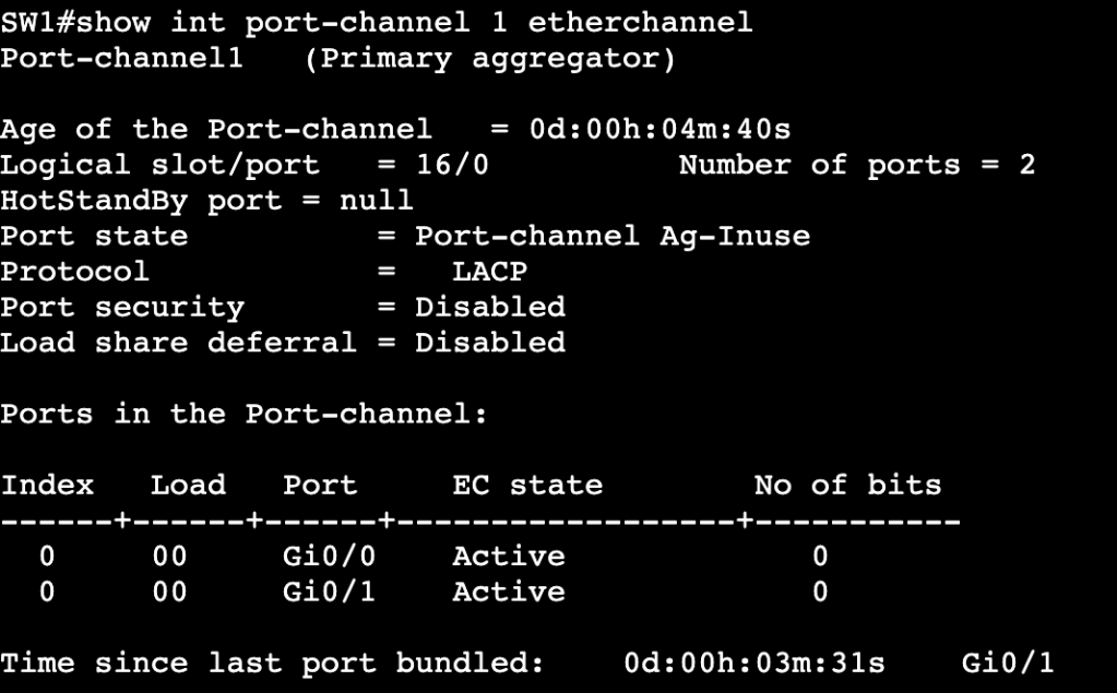
- Verification that port-channel is up can be done with show etherchannel summary or show int port-channel1 etherchannel:
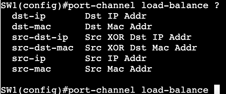
- Once verified, load balancing can be changed via ‘port-channel load-balance <method>
Layer 3 Etherchannel:
- Order of operation matters.
- When creating routed port-channel interface, do no switchport 1st on physical interfaces, then add them to LAG.
VLAN Trunking Protocol (VTP)
VTPv1/2
- Synchronizes VLANs between switches automatically
- Not a requirement
- Does not define broadcast domain
- Consists of VTP Server, Client, and Transparent mode
VTP Server
– Creates VLANs
– Advertises VLANs
– Installs VLANs from other advertisements – similar to client.
VTP Client
– Cannot create VLANs
– Can advertise VLANs
– Installs VLANs from other advertisements
VTP Transparent
– Creates locally significant VLANs
– Forwards VTP advertisements but does not listen or install VLANs from advertisements
Configuration Revision
– Sequence number for DB
– Highest Number wins
– VTP works towards having same DB number on all switches in VTP domain.
VTP Pruning
– Only in server and client mode
– Reduces necessary traffic over VTP peers
Configuration:
- Domain – router(config)#vtp domain mickx009.org
- Default configuration this will pass if trunk between two switches.
- Password – router(config)#vtp password CISCO
- Does not pass between VTP domain members.
- VTP updates will not pass if same password is not entered on both sides.
- Changing Mode – router(config)#vtp mode <server,client,transparent,off>
VTPv3 Enhancements:
- Security
- Primary Server – only device allowed to add to advertisements
- Advertisements
- MST
- PVLANs
- Extended VLANs
- Disabling
- Globally
- Per link
Configuration:
- Enabling VTPv3
- router(config)#vtp domain mickx009.org – before enabling v3
- router#vtp primary <vlan,mst> – On device you want as primary – only device allowed to update database.
Switching-VLANs
Ethernet Port Types:
Access Ports – Single VLAN, Untagged
Trunk – Multiple VLANs, tagged
Tunnel – Layer 2 Tunnel
Dynamic – Dynamic Trunking Protocol
Switched Virtual Interfaces – Virtual Layer 3 interface (VLAN interface)
Routed Interface – NO switchport
DTP Negotiation:
- Sometimes enabled by default on all trunk links.
- DTP Desirable Mode:
- Initiates Trunking
- ‘Switchport mode dynamic desirable’ on trunk interface
- ‘Switchport mode trunk’ on trunk interface
- DTP Auto Mode:
- Sits waiting for trunking negotiation
- Does not initiate DTP.
- Switchport mode dynamic auto
- Disabling:
- ‘Switchport nonegotiate’ – can only be used if dynamic auto is turned off.
- set as access or trunk port manually, then use switchport nonegotiate.
- ‘Switchport mode access’ – due to being access port.
- ‘Switchport mode dot1q-tunnel’ – due to being tunnel interface
- ‘Switchport nonegotiate’ – can only be used if dynamic auto is turned off.
- Can be seen with:
- ‘show interface switchport’
VLANs:
- Standard Range 1 – 1005
- VLAN1
- Default access and native (on trunk links)
- Cannot be pruned by VTP
- Cannot be deleted, can be manually pruned from trunks
- Should not be used for actual traffic.
- VLANs 1002 – 1005
- Legacy FDDI and Token Ring
- Cannot be deleted, can be manually pruned from trunks.
- Cannot be pruned by VTP
- Should not be used for actual traffic.
- VLAN1
- When assigning a port to a VLAN in access mode, if the VLAN does not exist in the database, the switch will create the VLAN automatically IF VTP mode is ‘Server’.
- Extended Range 1006-4094
- Can normally only be used in VTP Version3 and VTP Transparent.
- Not all of these IDs can be used. Some are reserved for internal resources.
- ‘show vlan internal usage’
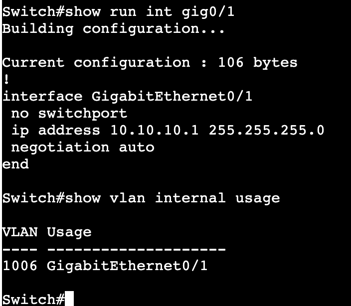
- The above image shows that when setting up a layer 3 interface with ‘no switchport’, internally one of these reserved IDs are used.
- vlan internal allocation policy <ascending/descending>
- Not all platforms do the same by default for reserved internal ID usage. Some go ascending, some go descending by default.
- Corner case – Change ascending to descending, or vice versa, if a VLAN ID like 4094 needs to be used and there are routed interfaces on switch.
Manual Trunk Pruning:
- Commands:
- switchport trunk allowed vlan add <#>
- switchport trunk allowed vlan remove<#>
- switchport trunk allowed vlan <#> – This will allow only the number(s) that are added to the command.
IOS-XE API
YANG:
- Yet Another Next Generation
- Data Modeling language used with NETCONF and RESTCONF.
- Originally came from Structure of Management Information next generation (SMIng).
- Uses tree like structure similar to XML.
- Modules start with top level ‘Container‘ objects.
- Ex. in networking – part of a router/switch. Container could equal ‘routing table’ or ‘interface’.
- Leafs – Descriptive objects that are within Containers.
- Ex. Name of interface, type of interface, state of interface.
- Each leaf has a ‘Type‘
- Ex. String or Boolean.
- Makes distinction between state related information and configuration items.
- RW – Read/Write
- RO – Read Only
NETCONF:
- Network Configuration Protocol
- Utilizes YANG data models and uses TCP 830
- Can decipher whether it’s dealing with operational/state data or configuration data.
- Encodes with XML or JSON.
- Common NETCONF Operations:
- <get>, <validate>, <get-config>, <lock>, <unlock>, <delete-config>.
- Uses RPC for messaging and SSHv2 – Need v2 enabled on Cisco boxes.
- NETCONF Agent – Router, Switch, NETCONF capable devices.
- NETCONF Manager – App used by operators.
- Datastores – Tables of data stored by the agent.
- <Running>
- <Startup>
- <Candidate>
Enabling NETCONF on Cisco IOS-XE:
- Enable SSHv2
- username cisco privilege 15 password cisco
- ip domain name mickx009.org
- crypto key generate rsa modulus 2048
- line vty – transport input ssh, login local (if local username is needed – if not AAA needs to be configured)
- ip ssh version 2
- Turn on NETCONF
- router(config)#netconf-yang
NETCONF/YANG with Python NCCLIENT:
NCCLIENT is a NETCONF Software Development Kit that operates in Python to assist with connecting to NETCONF Agents. After installing NCCLIENT via PIP, all that’s needed is for the library to be imported into Python scripts.
– ‘from ncclient import manager’
Connecting to a NETCONF enabled IOS-XE device in Python requires using the NCCLIENT manager.connect option, host, port, username and password. This can be accomplished with a python with statement.
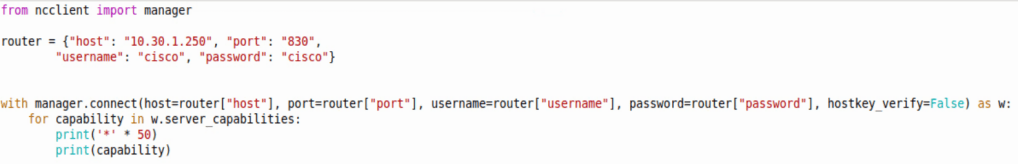
Above shows a script doing the following:
- Importing the NCCLIENT Manager
- Creating a dictionary specifying the router hostname, credentials, etc
- Using a with statement referring back to the dictionary for credentials, etc
- Creating NETCONF authentication into a variable that can be used moving forward
- And printing all NETCONF capabilities with 50 ‘*’ in between each line.
Making configuration changes on an IOS-XE device with NETCONF can be done with the NCCLIENT edit-config and a config template in a YANG model. Below is the IETF interfaces template in XML:
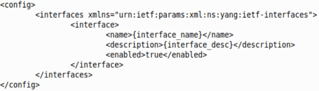
The template above can be opened in a Python script. With the Python format function, one can then fill in each ‘mustache’ as they see fit.
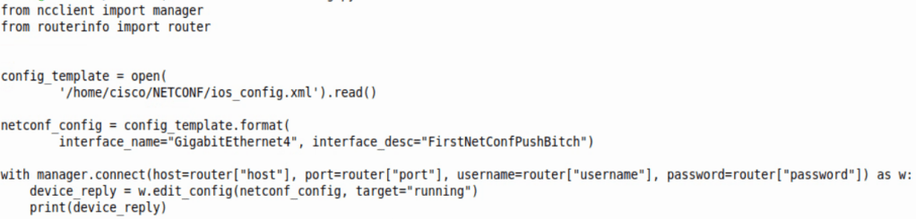
The script above does just that. From the top the script does the following:
- Imports NCCLIENT Manager
- Imports a dictionary with an IOS-XE router login/port/IP information
- Opens the template called ‘config_template’ which allows us to change the interface description.
- Changes the mustache variables to whatever is entered in “”
- Adds the change to the running container, or running config.
- Prints out the NETCONF reply, which is a simple ok
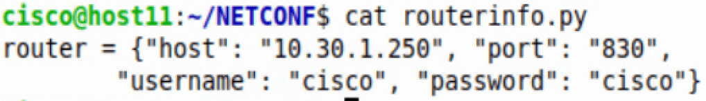
For clarity, the dictionary in the ‘routerinfo’ file looks like this:
RESTCONF:
- REST – Representational State Transfer
- REST APIs
- Runs HTTP verbs like GET, PUT, POST, DELETE
- Typically encoded in JSON or XML.
- CRUD
- Create
- Read
- Update
- Delete
- RESTCONF:
- Uses HTTPS instead of SSH
- Uses JSON primarily
- Sessionless, stateless
Enabling RESTCONF in IOS-XE:
- Enable SSHv2
- username cisco privilege 15 password cisco
- ip domain name mickx009.org
- crypto key generate rsa modulus 2048
- line vty – transport input ssh, login local (if local username is needed – if not AAA needs to be configured)
- ip ssh version 2
- Turn on RESTCONF
- router(config)#restconf
- ip http server
- ip http authentication local
- ip http secure server
RESTCONF/YANG with Postman
Connecting to a Cisco IOS-XE device with Postman requires the following:
Headers:
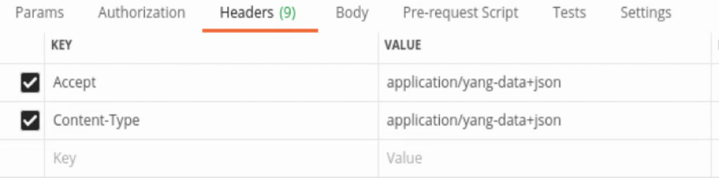
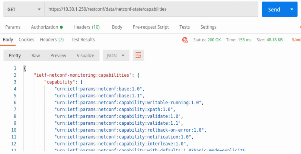
URL:

Notice we are going into the RESTCONF root and finding the NETCONF capabilities.
Authorization:
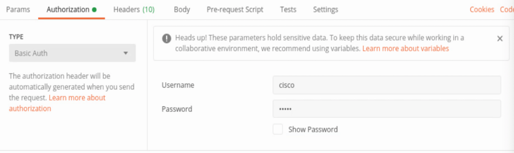
Notice the Basic Auth, username and password.
And when the GET request is sent, received in Postman is the list of capabilities below.
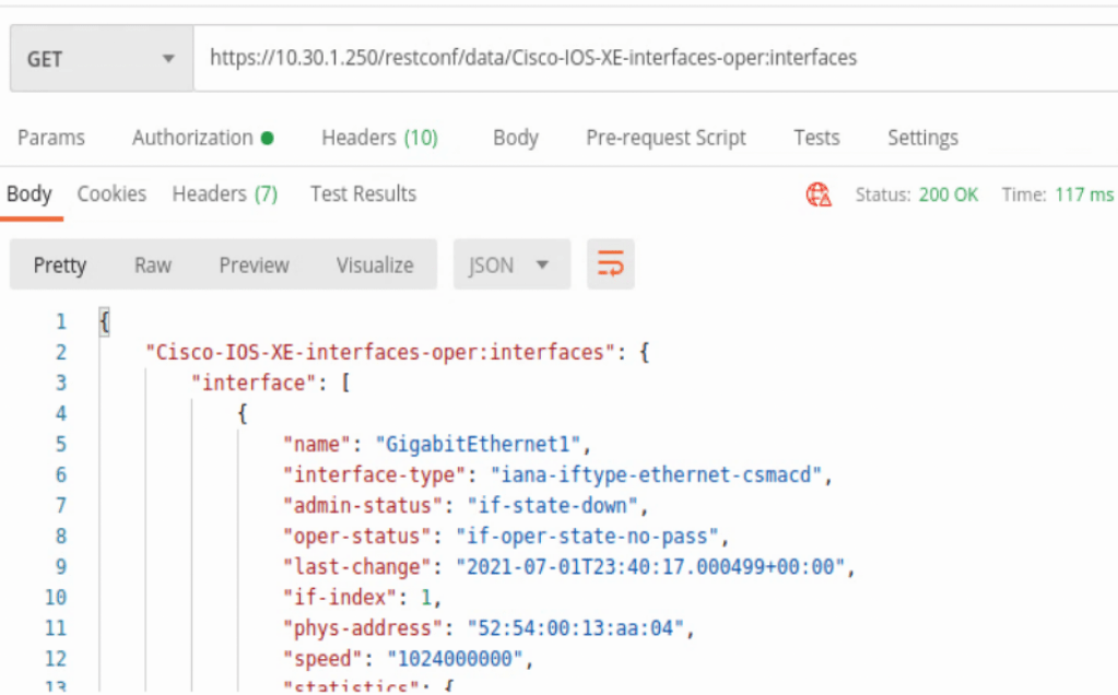
In the capabilities list the location /restconf/data/Cisco-IOS-XE-interfaces-oper:interfaces can be found. This will provide some detailed information about every interface on the IOS-XE device in JSON format.
Another interface example uses the location /restconf/data/Cisco-IOS-XE-native:native/interface/GigabitEthernet=<interface number>
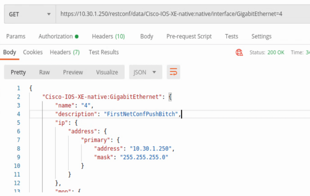
This will zoom into a specific IOS-XE interface with some slightly different data.
Those were all HTTP GET requests, but POSTS can be completed as well. All of the headers, authorization are the same, but now a body is needed to push to the device. Below is an example of adding a Loopback interface to the router.
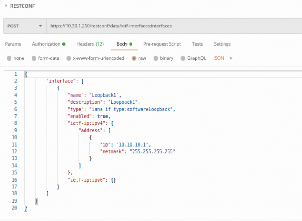
Above we have changed the GET to POST, then added a body onto what’s being sent to the IOS-XE device. It’s easiest to run a GET, copy how the YANG model is formatted, then add and change as needed in the body. At least for a simple task like adding a Loopback interface to a device.
This was the IETF formatting, but Cisco has their own models as well that can be found under the capabilities list.
To remove the Loopback that was just created, the request type needs to be changed to DELETE and the URL needs to be zeroed into the interface. When creating the interface, the URL used was below:
https://<host IP>/restconf/data/ietf-interfaces:interfaces
When deleting the interface, the URL is below:
https://<host IP>/restconf/data/ietf-interfaces:interfaces/interface=Loopback1
The response will be a ‘no content per below.

RESTCONF/YANG with Python Requests:
Connecting to an IOS-XE device with Python Requests is somewhat similar to connecting to other network devices via APIs. Requires the URL, headers, and creating response objects to gather and manipulate data on.
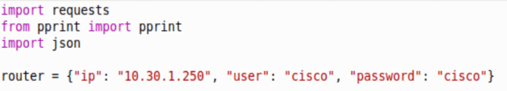
First we need to import requests, json, and pprint (optional), then create an object with the host IP and credentials.
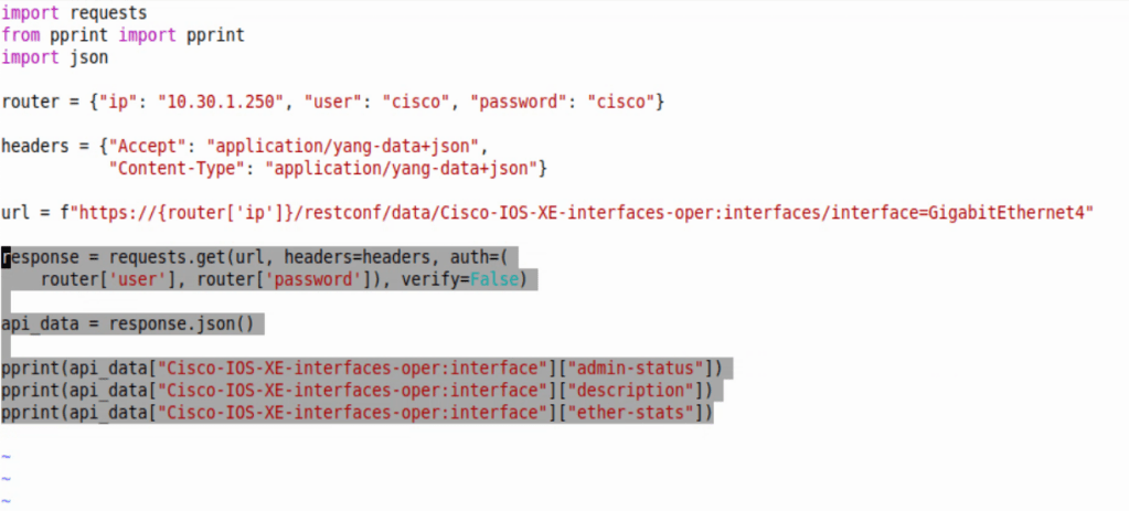
Next we’ll throw in the following headers in dictionary format as well, just like the router object above.

Then we’ll do the RESTCONF URL. This one is a native Cisco IOS-XE call.

After those basic items are added to the script, we then need to create the HTTP request that’s referencing the above items. Below is a GET request that references the router, headers, and url.
The response will be then formatted into a Python dictionary with the .json() addition, and then we’re printing the admin-status, description, and ether-stats.
Converting to dictionary allows us to easily cherry pick key values we want to print to screen. Below is an image of just a pprint of api_data – ie. pprint(api_data) at the bottom of the script.
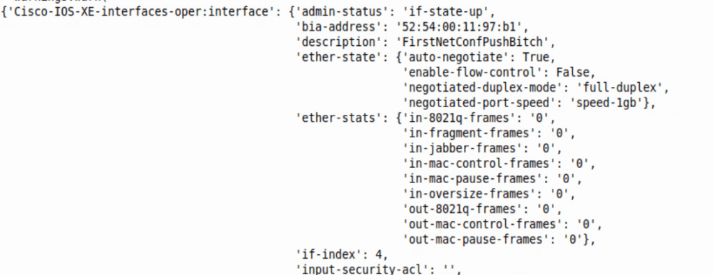
Adding the specific Keys to print can narrow down what we want back from the script – ie. pprint(api_data[“Cisco-IOS-XE-interfaces-oper:interface”][“admin-status”])
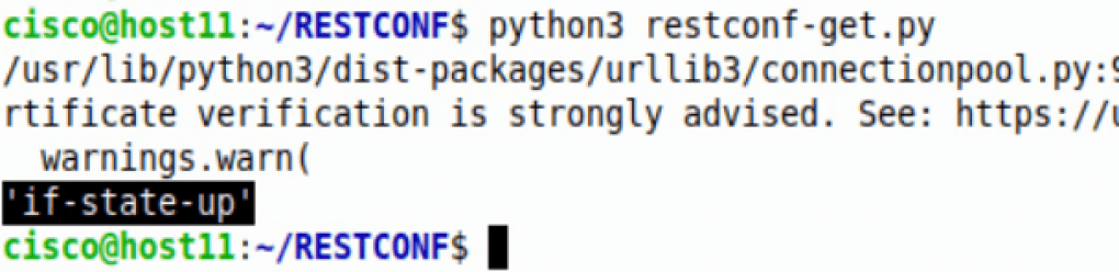
The HTTPS verification can be ignored. The response back was the value from Key ‘admin-status’.
On-change subscription with gRPC:
Enabling on-change subscription on an IOS-XE device requires below commands:
router(config)#telemetry ietf subscription 1
router(config-mdt-subs)#receiver ip address 10.30.1.50 57000 protocol grpc-tcp (or grpc-tls if TIG stack supports TLS)
router(config-mdt-subs)#source-address <source interface IP where data should be sent from>
router(config-mdt-subs)#filter xpath /cdp/ios-xe-oper:cdp-neighbor-details/cdp-neighbor-detail
router(config-mdt-subs)#stream yang-push
router(config-mdt-subs)#encoding encode-kvgpb
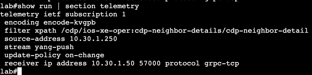
The above commands will allow an IOS-XE device to push streaming telemetry data to a TIG stack. The encode-kvgpb allows encoding for a TIG stack. The xpath is the xpath location where the switch is watching for changes. The update-policy on-change allows the switch to watch for changes to CDP neighbors and send that data to TIG if there are in fact changes.
DNA Center API
- Python Requests Library:
When leveraging DNA Center’s API with the requests library, the first thing that needs to be done is getting successfully authenticated. Lets first find the authentication endpoint within DNA Center’s GUI. Click on the search option in the top right corner of the homepage, then type in ‘API’.
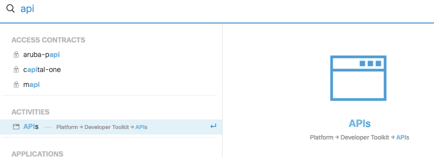
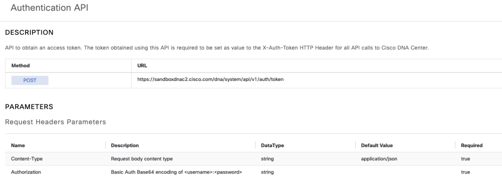
The very first API endpoint found in this section is for authentication.
After sending a valid username and password, DNAC will respond with a token that can be used for the remainder of the session in the call headers. Below is a bit of Python that shows this in action.

The Token, pulled from the authentication response, is labeled ‘token’ and is added to the headers with “x-auth-token”. At the bottom is a print statement to print out the token, which verifies authentication works properly. From here on out additional API calls can be entered below to gather information from DNAC.

The above calls the network device list endpoint and prints the response in JSON format.
Making API calls to DNAC with Postman is similar to the Python Requests method. We’re authenticating with Basic Auth, hitting the token API endpoint and receiving a Token. Moving forward that Token will be used to gather additional data from the API.
To authenticate and receive a valid Token from DNAC, the POST endpoint https://<dnacenterIPorFQDN/dna/system/api/v1/auth/token will be used, along with a username and password using basic Auth.

In the API documentation we’ll see that additional header variables need to be added.

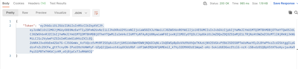
The Authorization will be Base 64 encoding, which essentially just needs a string Basic with a space, then the string YWRtaW46TWFnbGV2MTIz. After hitting Send to DNAC, we’ll receive the needed Token, per below:
Now moving forward, this Token needs to be added as a variable to each API call to DNA Center. Below is an example of getting a list of devices from DNA Center with Postman.
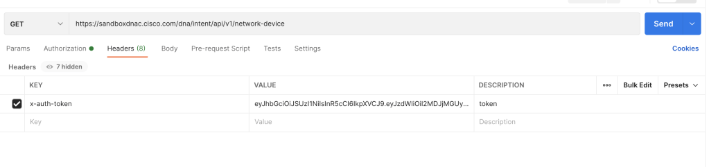

The process is very similar to Python requests library, but with a GUI that can give out code examples if needed.
