Used to leak traffic from VRF table to global table.
Requires static routing with next hop and global keyword
‘ip route VRF1 0.0.0.0 0.0.0.0 gig0/1 1.2.3.4 global
NAT statement is VRF aware.
ip nat inside source list 1 interface gig0/1 vrf VRF1 overload
The topology above shows a host on the internal RFC 1918 network 192.168.10.0/24. R6 will be doing some NAT functions to the ‘Internet’. R6 has private IP on the link to host, and public on the link to R4.
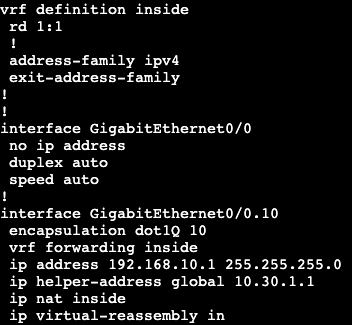
First configuration will be creating a new VRF and adding interface gig0/0.10 into it, which is the interface connecting to ‘Host’.
After adding the interface into the VRF we need to re-add the IP information like always.
This will cut off connectivity to the rest of the network because all of the routing is in R6’s global routing table, not the routing table associated with VRF ‘inside’.
To fix this we need to create a default route in the VRF to our next hop upstream, but specify the next hop is the global routing table. In addition, we’ll need to NAT traffic from the VRF to the outside interface. We’re going to do this with via an overload NAT/PAT.
Access-List permitting all
The default route here has a next hop of R4 and we’re pointing from the VRF to the global routing table.
And then we’re creating an overload NAT statement that references our VRF ‘inside’.
Now from our host we can reach past just our gateway/VRF on R6.
Destination IP rewrite may be used for redirection.
Normally configured as static mapping.
Port Address Translation
Many to one translation based on TCP/UDP ports.
Common overload.
Inside zone – networks translator wants to hide.
Inside local – Inside IPs before translation.
Inside global – Inside IPs after translation.
Outside zone – networks that are external to translator.
Outside Global – Original outside IP.
Outside Local – Outside IP after translation as its seen inside.
On the inside
Packets are first routed and then have sources translated.
Destination addresses are global so this is ok.
On the outside
Packets have destinations untranslated first.
Routing occurs after translation
Allows proper routing for returning packets with translated sources.
The topology above shows a host on the internal RFC 1918 network 192.168.10.0/24. R6 will be doing some NAT functions to the ‘Internet’. R6 has private IP on the link to host, and public on the link to R4.
Static 1:1
On R6 we need to first enter which interface is outside and which inside.
And the static 1:1 command:
Now if we telnet from ‘Host’ to ‘Internet’ at 8.8.8.8 and then look at the users on the box, we’ll see that the source IP address for the telnet session is the public NAT IP 96.76.43.140.
Can be seen on R6 that’s doing the NAT as well.
PAT/Overload:
1:1 has been erased off R6 and now we’re doing one to many PAT.
Access-list referencing the subnets that will use the PAT.
And the NAT statement that references the access list then specifies which interface we’re doing the port address translation on. ‘Overload’ at the end is needed as well.
Now when we run our telnet again to 8.8.8.8, we’ll see where we’re coming from.
We now get translated to R6’s ‘outside’ interface.
Policy NAT:
First we’re going to do a port forward from the ‘Internet’ router directly to the host. We’re going to pull an IP out of the IP block from the outside interface of R6. 96.76.43.141.
We are mapping the port 6500 and the IP of 96.76.43.141 to the inside port of 23 and the IP of 192.168.10.10. We can see this when looking at the nat translations from R6.
The topology above will have a DHCP server and relay setup. Host is going to be a DHCP client, R4 will be the DHCP server, and R6 will be our forwarder.
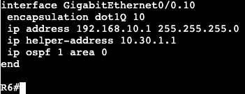
On R4 a DHCP pool has been configured for VLAN 10, the subnet in between R6 and eventually the host.
On the sub interface connecting to the host, we’ll need to add an IP helper statement towards the DHCP server, which allows DHCP requests to transit over L3 links.
The topology above has two gateways that will run GLBP, R6 and R4. The host is on the LAN side, 10.30.1.0/24, and the Internet has a loopback of 8.8.8.8.
The initial configuration only needs the one group command and VIP.
After this is on both LAN interfaces, the group is joined by the routers and we can see there are two forwarders, but only one active, R6.
To get the two routers both forwarding traffic, we need to run GLBP interface command for load-balancing.
Now when doing a traceroute from the host to 8.8.8.8, we see that the first attempt goes through 10.30.1.2 (R6), and a second attempt goes through 10.30.1.3 (R4). The round robin is every other and it goes by ARP request via client.
The above IP SLA and Tracking statement are still configured in R6 from the HSRP and VRRP configs. The tracking statement can get added to GLBP as well.
On R6 we’re going to decrement the default priority of 100 by 99 if the track fails, which is just pinging 8.8.8.8 on the ‘Internet’ router.
The topology above has two gateways that will run VRRP, R6 and R4. The host is on the LAN side, 10.30.1.0/24, and the Internet has a loopback of 8.8.8.8.
VRRP configuration is very straightforward and similar to HSRP. I entered the preempt command and it does not show up in a show run interface. That’s because it’s on by default.
Above shows the virtual MAC VRRP is using.
The authentication is the same as HSRP, but I created a new key chain for practice. This is the same for the tracking statement. If 8.8.8.8 on internet router goes down, the VRRP active member changes over.
Which shows on R4 when I shutdown the loopback interface.
Uses terms master/backup as opposed to active/standby
Other concepts are similar
Uses transport protocol 112 and 224.0.0.18
Virtual MAC is 0000.5e00.01xx
Preemptive by default.
GLBP
Cisco Proprietary
Extends HSRP functionality to support load balancing.
Transport via UDP 3222 and 224.0.0.102
Every physical gateway can be active.
Called active virtual forwards (AVF)
Each AVF is assigned virtual MAC.
One gateway responds to ARP requests for GLBP IP
Called Active Virtual Gateway (AVG)
ARP response uses virtual MACs of AVFs to implement load-balancing.
LOAD BALANCING IS COMPLETED BY CLIENT, NOT FLOW.
AVG
Elected based on priority
By default only AVF, all others standby.
No AVG preemption by default.
Enable using glbp preempt
To enable load balancing:
‘glbp xxx load-balancing weighted’
Assign weights with ‘glbp xxx weighting Y’
Weight can be adjusted based on object tracking.
FHRP enhanced object tracking
Gateway recovery relies on correct failure detection.
eg. FHRP keepalives or BFD.
What if southbound link is up but northbound is down?
REsult is Active/master maintains bizz as usual.
Solution:
Setup IP SLA with FHRP.
Object tracking is bound to priority.
Decrement priority if object is down.
Assumes preemption is configured.
IPv6 support
HSRPv2
Increases group range
adds new dedicated transport add 224.0.0.102
Doesn’t overlap with ALL ROUTERS
Adds IPv6 support.
Enabled with int level standby version 2
VRRPv3
RFC5798
enabled with global ‘fhrp version vrrp v3’
HSRP Config:
From the topology above, we’re going to run HSRP between R6 and R4. This will provide redundancy for the host to internet if one of the gateway routers were to fail.
R6 and R7 are the gateways for the LAN network 10.30.1.0/24. The host is using a default gateway of 10.30.1.1 and R6/R7 will setup that VIP. To get HSRP running it only requires these commands on each box:
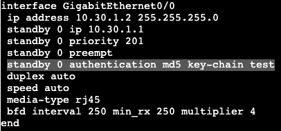
Note each physical interface has an IP in the lan – 10.30.1.2 and 10.30.1.3.
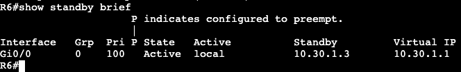
On the host now we can see the Virtual MAC address for 10.30.1.1 and on R6 we can see which router is the active node:
R6 is active and R4 is standby.
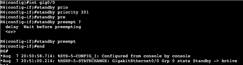
If we want to switch which router is active, we’ll add the priority command that is higher than the default 100, which is what R4 is currently using.
Pre-emption is not enabled, which means this will not take affect until the HSRP election comes up again.
After I shutdown the LAN interface on R6, R4 became the active router. Now if I change the priority of R6 to something higher than 200, then enable preemption, R6 will take over as active again.
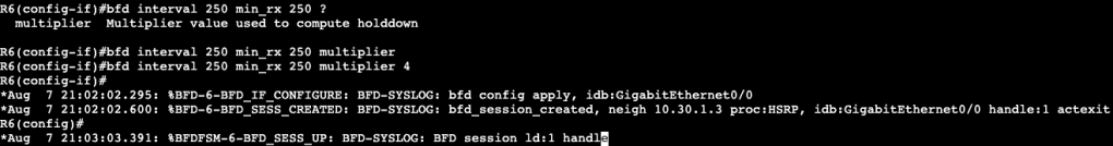
Often times two devices running HSRP are doing this process for multiple gateways/VLANs/Subnets, and each process is running the multicast keepalives between the two routers. In order to minimize this chatter and CPU overhead, BFD can be used between the two boxes for ALL processes.
Under the interface on R6 we add the command ‘bfd interval 250 min_rx 250 multiplier 4’ and immediately BFD starts working with HSRP. The same command gets added to R4.
By default in IOS-XE, BFD is already enabled for HSRP if you turn it on under the interface that’s running HSRP.
Authentication:
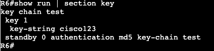
If we want to add authentication for an extra layer of security between HSRP nodes, the config is below.
For MD5 authentication we’ll first create a key chain in global config, then apply that keychain to the authentication string under the standby interface command.
Object Tracking:
In the topology, we have the ‘Internet’ host with a loopback of 8.8.8.8 that we’re going to use as an example of object tracking. R6 is going to run an ongoing ping to 8.8.8.8 and if it fails to reach the destination, it will be configured to leave the HSRP active state.
The IP SLA has been configured, but not applied to HSRP yet. This needs to be added under the interface running the VIP.
Decrement means that if the IP SLA tracking fails, decrement the router priority by 101. The priority would then be 100, lower than R4’s 200.
The last step is configuring the tracking object. The tracking object configuration is below:
Below is what happens when the loopback interface on ‘Internet’ goes down.
R4 took over as active HSRP and the Standby router priority is now 100 instead of 201.
Legacy Hub and Spoke, QoS was applied per VC or DLCI
With DMVPN, all spokes exist on same Tunnel and underlay.
Per-Tunnel QoS for DMVPN fixes this.
Spoke signals QoS group to hub through NHRP.
‘ip nhrp attribute group <group>’
Group name must match between hub and spoke.
QoS group name maps to QoS template on hub.
‘nhrp map group <group> service-policy output <policy>’
Result is that each spoke has a separate QoS policy.
Verified as ‘show policy-map multipoint on the hub.
Per Tunnel QoS with DMVPN is applied via group commands on each hub and spoke.
Hub:
Spoke:
You create a group that has a Service-Policy applied to it, then on the spoke you’re joining a group to receive the attribute of QoS. Using groups allows the hub to push out a service policy to the spokes granularly. In a way it acts as a controller.
The group and service-policy can be seen by running a ‘show dmvpn detail’.